Using a Servo Controller with an ESP32
- Why a Servo Controller?
- Wiring the PCA9685
- Installing The Servo Library
- First Example Servo Controller Program
- Example Servo Controller for Many Servos
- Example Servo Controller for Robot
- Calibrating and Programming Servo Positions
- What’s next?
But before we start, check out our ESP32 Servo tutorial to get all the basics. If you only need to control a few servos, that previous tutorial will be the cheapest and fastest option. However, if you’re looking to make a biped, hexapod, or some crazy tentacle robot with many servos, you’ll need a servo controller – and this tutorial to speed you right through it.
Why a Servo Controller?
The ESP32 has a limited number of pins. At most, you can control a dozen servos, assuming you don’t need any ESP32 pins for literally anything else. Additionally, the ESP32 you purchased very likely doesn’t have a high current power bus, so you’d need to wire up a dozen plus servos yourself – a pain!
So, what if you needed, say, 16 servos? Or 50? What then?
Servo_Controller has entered the chat.
The easiest solution is to use a daughter board dedicated to servos, linked to your ESP32 (the motherboard) via I2C. We’re going to use the PCA9685 servo controller chip. Looking through Amazon there are a half dozen different merchants selling the same exact board, just with their own brand logo and various minor tweaks.
I chose the Adafruit 16-Channel 12-bit PWM/Servo Driver.


Wiring the PCA9685
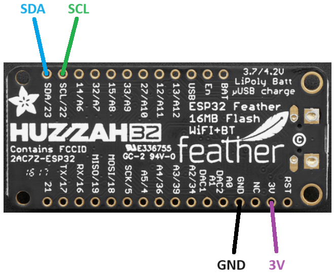
Wiring is straightforward. You got 4 wires going to your ESP32 – 3.3V and ground, plus two wires for I2C. Then you got two wires from your servo battery, power and ground. And finally, you plug in your servos to the bus.
Note: I2C is pronounced ‘eye squared C.’ It’s actually I²C, but I honestly can’t find that little ² on my keyboard. I’m not even sure how I just typed it! So, it’ll be I2C for this tutorial.
Wiring chart + diagram follows:
| Step | |
|---|---|
| GND x2 | Goes to (-) negative of your servo battery, and ground of each servo. |
| SCL | Goes to SCL pin of ESP32. |
| SDA | Goes to SDA pin of ESP32. |
| VCC | Goes to 3.3V voltage regulator output from ESP32 board. |
| V+ x2 | Goes to (+) positive of your servo battery (4.8V-6V), and power of each servo. |
| PWM | Pins 0-15 go to the signal wire of each servo. |

Don’t bother with the servo battery connection at top. For some reason, at least on the unit I received, it’s not wired to the servo power bus (?!).
What if you wanted more than 16 servos? You can add many additional servo controller boards to the same I2C bus. Refer to the controller board documentation on using the jumpers to select I2C addresses.
In the below image, I have the battery connected to the power bus via port 15, and 12 servos connected from port 0 to port 11.

Below is how to wire the ESP32. Be sure to give it appropriate power as per the manual for the ESP32 you choose to use.
Installing The Servo Library
Now that you got your hardware wired up, let’s get onto the software side of things.
Load up your Arduino IDE, and go to:
Tools => Manage Libraries
and type in PCA9685 into search.
Download and install the library by Peter Polidoro:

Note: check out the ESP32 PCA9685 library (by Peter Polidoro) on Github for more info.
First Example Servo Controller Program
Let’s try out the first built in example program that comes with the library. It’s a bit over-complicated in my opinion, and very oddly only has code for a single servo, but it is what it is.
Go to:
File => Examples => PCA9685 => ServoController

Your screen should now look like the below screenshot. Click on the tab, Constants.cpp. This file is where you customize it for your specific hardware.

I added comments below to explain what you’re looking at. Change any values needed, then run the code. Your servo on Channel 0 should rotate back and forth.
//time spent doing nothing, before restarting loop
const size_t loop_delay = 100;

//the pin your servo is connected to
const PCA9685::Channel channel = 0;

//starting servo position
const PCA9685::DurationMicroseconds servo_pulse_duration_min = 900;

//maximum servo position
const PCA9685::DurationMicroseconds servo_pulse_duration_max = 2100;

//minimum servo position
const PCA9685::DurationMicroseconds servo_pulse_duration_increment = 100;
Example Servo Controller for Many Servos
The above default example uses a servo controller that can control 16 servos, but only has code for literally only one servo (?!).
Let’s add a few more servos to that example to get you started.
In Constants.h, add two (or more) additional Channels. In this case I added left and right. Think of it as ‘left wheel’ and ‘right wheel,’ and a third servo called ‘channel’.
extern const PCA9685::Channel channel;
extern const PCA9685::Channel left;
extern const PCA9685::Channel right;
Next, we need to define the corresponding channel numbers on the daughterboard PCB. Add these two lines to Constants.cpp, and plug your servos in to #0, #10, and #11 on the PCB.
const PCA9685::Channel channel = 0;
const PCA9685::Channel left = 10;
const PCA9685::Channel right = 11;
Lastly in your .ino file, in the loop(), tell the two new servos to do something. The red numbers represent signal pulse widths measured in milliseconds, corresponding to servo angles. Different servo brands/models use different numbers, but 500ms to 1500ms is the typical range.
pca9685.setChannelServoPulseDuration(constants::channel,1100);
pca9685.setChannelServoPulseDuration(constants::left,800);
pca9685.setChannelServoPulseDuration(constants::right,1900);

delay(1000);

pca9685.setChannelServoPulseDuration(constants::channel,700);
pca9685.setChannelServoPulseDuration(constants::left,1800);
pca9685.setChannelServoPulseDuration(constants::right,600);

delay(1000);
Example Servo Controller for Robot
Now that you have a good understanding of using a servo controller, let’s go for something more complicated. In this following example, imagine a robot with two arms, a rotating head, and wheels to drive around. In total 13 servos, each of which needs to go through a pre-programmed list of motions to do the Macarena (or whatever dance that is popular today).
Said robot would look something like the video below, a robot I built a very very long time ago – but recently upgraded with modern electronics. For this tutorial I have it smoothly transitioning between a set of pre-programmed positions for a basic demo. The code interpolates between each final position – so only the end points need to be hard coded. The lack of stereotypical jerky stop-start robot motion is very important to have. It protects servo gears from breaking under high dynamic forces.

Let’s get started with adding this code to your project
Start a new project in your IDE called macarena.
Create two files in the project: macarena.ino, and servos.h.
Paste the below code into your .ino file:
/*
 * Code written by John Palmisano
 * in coordination with programmingelectronics.com
 * May 2024
 * license: any use of this code requires retaining this citation

*/
#include <string>
#include <ArduinoJson.h>
#include "servos.h"

void setup() {
  //small delay for proper power up

  delay(150);
  Serial.begin(115200);

  Wire.begin(26, 27);//declare pins for I2C

//  all_servos_off();
  Serial.println();
  Serial.println("Starting up...");

  //wifi_setup();//needs 100ms time for bootup or the reset pin will trigger; kills Rx with USB!
  delay(100);
  servos_setup();
  delay(10);
  servo_goto_init_pos();
  delay(50);

}

void loop() {

  ////////////////////////SERVO CALIB CODE//////////////////////////
  //while(1)
  //  servo_calib();
  //////////////////////////////////////////////////////////////////

  //command servos to go through each of
  //the pre-programmed position lists

  Serial.println("Going through dance routines.");
  for(uint8_t i=0;i<200;i++)

    {
    servo_goto_pos(servo_init_pos);
    servo_pulse_all();
    delay(15);
    }

  for(uint8_t i=0;i<180;i++)
    {

    servo_goto_pos(servo_fly_pos);
    servo_pulse_all();
    delay(15);

    }

  for(uint8_t i=0;i<180;i++)

    {

    servo_goto_pos(servo_attack_pos);
    servo_pulse_all();
    delay(15);

    }

  for(uint8_t i=0;i<130;i++)

    {

    servo_goto_pos(servo_prayL_pos);
    servo_pulse_all();
    delay(15);

    }

  for(uint8_t i=0;i<130;i++)

    {

    servo_goto_pos(servo_prayR_pos);
    servo_pulse_all();
    delay(15);

    }

  for(uint8_t i=0;i<130;i++)

    {

    servo_goto_pos(servo_prayL_pos);
    servo_pulse_all();
    delay(15);

    }

  for(uint8_t i=0;i<130;i++)

    {

    servo_goto_pos(servo_prayR_pos);
    servo_pulse_all();
    delay(15);

    }

}
Next, paste the below code into your header file, servos.h.
Each section of code is commented to explain what it does.
The most important lines are the servo position arrays, servo_XXXX_pos[10]. There are 10 positions in the array, one defined for each servo (there are 10 servos being used in this example… no wheel action). The robot moves by first starting with one array, for example servo_init_pos, and all servos moving to their corresponding defined position in that array. Then the robot is told to move to new positions in a different array, for example servo_attack_pos. Each value (position) in the arrays was manually determined using my servo ‘calibration’ code. I’ll explain in the next section how to calibrate.
// get commands from:
// https://github.com/janelia-arduino/PCA9685/blob/master/src/PCA9685/PCA9685.cpp

#include <PCA9685.h>

PCA9685 pca9685;
const uint16_t servo_time =20;//time between servo angle changes
uint64_t  servo_last_time =0;//last time servo was changed

//servo channel (name of each servo, head, arm, hand, etc.)

#define head_hor            0
#define head_ver            1
#define left_base_hor       2
#define left_base_ver       3
#define left_elbow          4
#define left_hand           5
#define right_base_hor      6
#define right_base_ver      7
#define right_elbow         8
#define right_hand          9
#define wheel_left          10
#define wheel_right         11

//current servo angle (stores position of current angle)

uint8_t head_hor_pos      = 64;
uint8_t head_ver_pos      = 100;
uint8_t left_base_hor_pos = 75;
uint8_t left_base_ver_pos = 134;
uint8_t left_elbow_pos    = 65;
uint8_t left_hand_pos     = 60;
uint8_t right_base_hor_pos= 51;
uint8_t right_base_ver_pos= 0;
uint8_t right_elbow_pos   = 67;
uint8_t right_hand_pos    = 90;
uint8_t wheel_left_pos    = 0;
uint8_t wheel_right_pos   = 0;

//a list of different positions for all servos
uint8_t servo_init_pos[10]={64,70,78,138,123,61,51,5,0,45};
uint8_t servo_attack_pos[10] ={81,100,114,98,123,26,16,44,20,90};
uint8_t servo_fly_pos[10] ={68,60,135,139,48,69,10,7,89,10};
uint8_t servo_prayL_pos[10] ={65,50,71,0,29,44,53,77,89,45};
uint8_t servo_prayR_pos[10] ={75,70,75,65,79,44,53,150,120,45};

//run this is your setup()

void servos_setup(void)

{

  pca9685.setupSingleDevice(Wire,0x40);

//  pca9685.setupOutputEnablePin(constants::output_enable_pin);
//  pca9685.enableOutputs(constants::output_enable_pin);
//  pca9685.disableOutputs(constants::output_enable_pin);

  pca9685.setToServoFrequency();

}

//converts desired angle to servo pulse frequency
//scale a number from 0 - 180 to 800 - 2000
//note, each servo type has different scaling

uint16_t angle_2_ms(uint8_t angle)

  {

  return 2000*angle/180+800;

  }

//converts desired rotational speed (-100 to 100) to servo pulse frequency
uint16_t speed_2_ms(int8_t speed)

  {

  return 1200*((speed+100)/200)+800;

  }

//sends a command to all servos

void servo_pulse_all(void)

  {

  pca9685.setChannelServoPulseDuration(head_hor,angle_2_ms(head_hor_pos));
  pca9685.setChannelServoPulseDuration(head_ver,angle_2_ms(head_ver_pos));
  pca9685.setChannelServoPulseDuration(left_base_hor,angle_2_ms(left_base_hor_pos));
  pca9685.setChannelServoPulseDuration(left_base_ver,angle_2_ms(left_base_ver_pos));
  pca9685.setChannelServoPulseDuration(left_elbow,angle_2_ms(left_elbow_pos));
  pca9685.setChannelServoPulseDuration(left_hand,angle_2_ms(left_hand_pos));
  pca9685.setChannelServoPulseDuration(right_base_hor,angle_2_ms(right_base_hor_pos));
  pca9685.setChannelServoPulseDuration(right_base_ver,angle_2_ms(right_base_ver_pos));
  pca9685.setChannelServoPulseDuration(right_elbow,angle_2_ms(right_elbow_pos));
  pca9685.setChannelServoPulseDuration(right_hand,angle_2_ms(right_hand_pos));

//  pca9685.setChannelServoPulseDuration(wheel_left,speed_2_ms(wheel_left_pos));
//  pca9685.setChannelServoPulseDuration(wheel_right,speed_2_ms(wheel_right_pos));

  }

void servo_print_all(void)

  {

  Serial.printf("ns: %u",head_hor_pos);
  Serial.printf(",%u",head_ver_pos);
  Serial.printf(",%u",left_base_hor_pos);
  Serial.printf(",%u",left_base_ver_pos);
  Serial.printf(",%u",left_elbow_pos);
  Serial.printf(",%u",left_hand_pos);
  Serial.printf(",%u",right_base_hor_pos);
  Serial.printf(",%u",right_base_ver_pos);
  Serial.printf(",%u",right_elbow_pos);
  Serial.printf(",%u",right_hand_pos);

//  Serial.printf(",%u",wheel_left_pos);
//  Serial.printf(",%u",wheel_right_pos);

  }

//moves all current servo positions by 1 degree
//closer to desired position list

void servo_goto_pos(uint8_t *pos_list)

  {

  //Serial.print("nreading in servo position list");
  if(head_hor_pos>pos_list[0])
    head_hor_pos--;

  else if(head_hor_pos<pos_list[0])
    head_hor_pos++;

  if(head_ver_pos>pos_list[1])
    head_ver_pos--;

  else if(head_ver_pos<pos_list[1])
    head_ver_pos++;

  if(left_base_hor_pos>pos_list[2])
    left_base_hor_pos--;

  else if(left_base_hor_pos<pos_list[2])
    left_base_hor_pos++;

  if(left_base_ver_pos>pos_list[3])
    left_base_ver_pos--;

  else if(left_base_ver_pos<pos_list[3])
    left_base_ver_pos++;

  if(left_elbow_pos>pos_list[4])
    left_elbow_pos--;

  else if(left_elbow_pos<pos_list[4])
    left_elbow_pos++;

  if(left_hand_pos>pos_list[5])
    left_hand_pos--;

  else if(left_hand_pos<pos_list[5])
    left_hand_pos++;

  if(right_base_hor_pos>pos_list[6])
    right_base_hor_pos--;

  else if(right_base_hor_pos<pos_list[6])
    right_base_hor_pos++;

  if(right_base_ver_pos>pos_list[7])
    right_base_ver_pos--;

  else if(right_base_ver_pos<pos_list[7])
    right_base_ver_pos++;

  if(right_elbow_pos>pos_list[8])
    right_elbow_pos--;

  else if(right_elbow_pos<pos_list[8])
    right_elbow_pos++;

  if(right_hand_pos>pos_list[9])
    right_hand_pos--;

  else if(right_hand_pos<pos_list[9])
    right_hand_pos++;

/*

  if(wheel_left_pos>pos_list[10])
    wheel_left_pos--;

  else if(wheel_left_pos<pos_list[10])
    wheel_left_pos++;

  if(wheel_right_pos>pos_list[11])
    wheel_right_pos--;

  else if(wheel_right_pos<pos_list[11])
    wheel_right_pos++;

*/

  //wheel_left_pos    = pos_list[10];
  //wheel_right_pos   = pos_list[11];
  servo_pulse_all();

  }

//commands all servos to move to init position
void servo_goto_init_pos(void)

  {

  for(uint8_t i=0;i<200;i++)

    {

    servo_goto_pos(servo_init_pos);
    servo_pulse_all();
    delay(15);

    }

  }

//below code allows you to use letters on keyboard
//to move servos; helps with pre-programming positions
//into a list, and also to determine servo end points

void servo_calibrate(void)

  {

  if (Serial.available())

    {

    char receivedChar = Serial.read();
    Serial.print(receivedChar);

    if (receivedChar == 'q')
      head_hor_pos++;

    else if (receivedChar == 'a')
      head_hor_pos--;

    else if (receivedChar == 'w')
      head_ver_pos++;

    else if (receivedChar == 's')
      head_ver_pos--;

    else if (receivedChar == 'e')
      wheel_left_pos++;

    else if (receivedChar == 'd')
      wheel_left_pos--;

    else if (receivedChar == 'r')
      wheel_right_pos++;

    else if (receivedChar == 'f')
      wheel_right_pos--;

    else if (receivedChar == 't')
      left_base_hor_pos++;

    else if (receivedChar == 'g')
      left_base_hor_pos--;

    else if (receivedChar == 'y')
      left_base_ver_pos++;

    else if (receivedChar == 'h')
      left_base_ver_pos--;

    else if (receivedChar == 'u')
      left_elbow_pos++;

    else if (receivedChar == 'j')
      left_elbow_pos--;

    else if (receivedChar == 'i')
      left_hand_pos++;

    else if (receivedChar == 'k')
      left_hand_pos--;

    else if (receivedChar == 'o')
      right_base_hor_pos++;

    else if (receivedChar == 'l')
      right_base_hor_pos--;

    else if (receivedChar == 'z')
      right_base_ver_pos++;

    else if (receivedChar == 'x')
      right_base_ver_pos--;

    else if (receivedChar == 'c')
      right_elbow_pos++;

    else if (receivedChar == 'v')
      right_elbow_pos--;

    else if (receivedChar == 'b')
      right_hand_pos++;

    else if (receivedChar == 'n')
      right_hand_pos--;

    servo_print_all();

    }

  servo_pulse_all();

  }

void servo_calib(void)

  {

  //if timer overflow
  if(millis() < servo_last_time)

    {

    servo_last_time = millis();
    Serial.print("nprintOVERFLOW");

    }

  if(millis()-servo_last_time > servo_time)

    {

    servo_last_time=millis();
    servo_calibrate();

    //servo_pulse_all();
  //servo_goto_pos(servo_init_pos);

    }

  }
Upload and run the code on your robot, modifying it to fit your robot design.
Calibrating and Programming Servo Positions
Imagine the above robot, with its head and arms, and you want it to do the Macarena. You’d need to individually program each of the 10+ servos through several dozen different positions to complete the dance. That’s potentially hundreds of positions, a lot of work! To make life easier, here is a script I wrote to use your keyboard to control each individual servo. You can move each servo to the exact position you desire, then record the location as a number. That number can then be transferred into arrays of various positions. Just a few minutes of effort per array needed.
Let’s get started.
First, in the .ino file from above, uncomment these two lines. This forces the robot into ‘calibration’ mode.
////////////////////////SERVO CALIB CODE//////////////////////////

  while(1)
    servo_calib();

  //////////////////////////////////////////////////////////////////
Now in servos.h, scroll down to void servo_calibrate(void) and look for the following code. Notice q, a, w, s, etc.
...
    if (receivedChar == 'q')
      head_hor_pos++;

    else if (receivedChar == 'a')
      head_hor_pos--;

    else if (receivedChar == 'w')
      head_ver_pos++;

    else if (receivedChar == 's')
      head_ver_pos--;
...
If you enter any of these letters on your keyboard via the Arduino IDE Serial Monitor (your ESP32 should be connected to Serial via USB), the specified servo will then move. You will then see a list of numbers printed to your screen, telling you positions (angles) of all servos at that moment. If you’re happy with all positions, copy/paste the number list to the arrays from earlier, such as:
uint8_t servo_init_pos[10]={64,119,78,138,123,61,51,1,0,90};
Once all your arrays are defined, comment out the calibration while() loop, upload and run the code on your robot, and you’re done!
What’s next?
Future tutorials will use this robot to demonstrate robot hand-eye coordination. Once you go through the core building blocks of arm manipulation and computer vision, I’ll show you how to use the ESP32, a camera, and robot arms to track and grab objects in real time.
Stay tuned!


