Arduino Linear Actuator Control :: Member Project
Ever need to measure something within a thousandth of an inch? Repeatedly?
For Bill, he found using a tape measure to be less accurate as he would have liked. So to solve this problem, he used Arduino to create his very own linear actuator stop, which can measure lengths with an accuracy up to the thousandth of an inch!
That’s some pretty good accuracy compared to measuring with a tape measure. Read on to find out how Bill turned a small interest in Arduino into this really cool project!
So Bill, can you tell us a little bit about what you built?
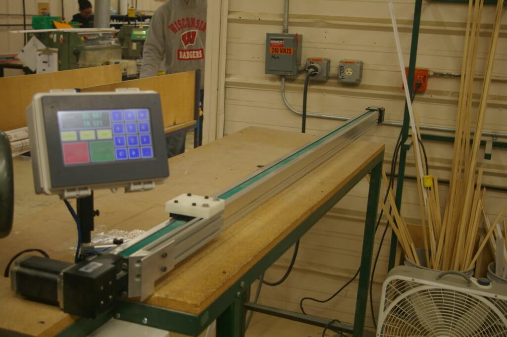
I made a linear actuator position stop. It can be used on a saw, drill, or any machine where you want to precisely position material.
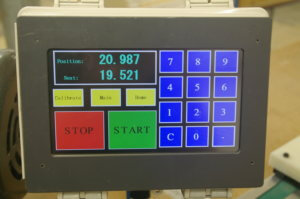
You can input the length of the part you want to cut and the stop will move to that position, right to the thousandth of an inch.
Thousandth of an inch, that’s incredible!
Yes, typically you would have to use a tape measure and pencil to mark a spot, clamp a block to act as a stop, then do a sample cut. Then you would have to move the stop if it were not positioned correctly. With this positioner, the first cut is accurate.
It’s also quite difficult to read a number like 24.763 on a tape measure.
And how is it powered?
The actuator is powered using a wall outlet
So what type of Arduino board does your project use?
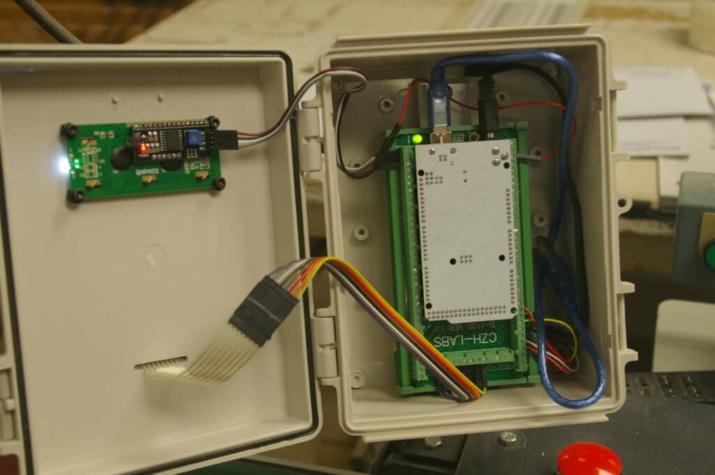
I am using an Arduino Mega 2560 clone.
And what other components did you use?
A button, servo motor, stepper motor, keypad, switch, enclosure, and an LCD display
Why did you build this linear actuator stop?
Well, I saw an article in a magazine that showed an Arduino board being used to control a wood router position. I had never even heard of an Arduino before reading that article, and it looked very interesting and affordable.
I work in a factory that uses commercially available linear actuator position stops. They work great but can cost anywhere between $6,000 to $10,000 each. I thought that with the Arduino, I could maybe make a much cheaper version, so I bought an Arduino starter kit off of Amazon, just to get my feet wet.
It looks like you were successfully able to make a far more affordable version!
Indeed! It seems like you can make almost anything with these Arduinos.
I started off with making a small prototype actuator to prove to myself that I could do it. I took it to my workplace and talked my boss into allowing me to make a full-sized unit.
I also made one for my home shop. I have now made several of these and am starting to make them for other divisions in our company.

I have actually made several changes to my design. At first, I used a stepper motor to drive the actuator, which worked, but this would sometimes lose counts.
I made the next version with servo motors. This fixed the issue with the missed steps. The first several positioners I made were directly driven from the motor to the pulley driving the belt actuator.
Since then, I have since added a gearbox between the motor and pulley with great results. Now, I am able to use a smaller powered motor. My next goal is to improve the user interface from a stick-on keypad with a small LCD screen to a 7-inch touchscreen.
You have some big plans in place for updates, that’s awesome. Amazing that you had no prior experience with Arduino before this!
Yeah, since I had no prior programming experience with Arduino, I had a lot to learn. The first versions I made were based on programs I found on the internet.
So was the training at Programming Electronics Academy able to help you build your Arduino skills?
Yes, it did! When I looked at other people’s code, I really didn’t understand things like for loops, while loops, if statements, matrix’s, and the general rules of Arduino programming.
The training from Programming Electronics Academy is very well laid out and easy to understand.
What were some of the other struggles you encountered as you worked through this project?
In the original design, which used a stepper motor (Euclid Machine and Design), I had to modify the program to work with my hardware.
When I upgraded to the servo motor I also found another program on the internet (neo7cnc.com). It also needed a few changes to work with my hardware.
After making 6 actuators I wanted to try and make one with a touchscreen. I knew it was going to be a lot more programming, but I was up for a challenge. After about a month of trying to make it work, I realized how big a challenge it was.
The screen needed to be programmed for every little detail shown on the screen and after I got the look I wanted, I was at about 600 lines of code. When I tried to make the buttons actually work I learned it was probably going to take thousands of line of code to work.
I knew I had to find an easier way, so I found the Nextion touchscreens and tried them (which made such a huge difference). It still took me a while to make it look and work the way I wanted, but it was so much easier and with way fewer lines of code.
Plus all the touchscreen code is run on the Nextion itself and that frees up the Arduino a lot.

I learned a lot about programming from your Programming Electronics Academy. Before that, I used Youtube often.
Until I tried your course I really didn’t understand much of what I was seeing in other peoples codes.
I have learned that there are many ways to write code to make a project do what you want it to do. I know I have a lot to learn, but I am starting to be able to write some of my own code now instead of relying on other people’s code.
Arduino Code:
Bill was kind enough to share the code files he has been using for his linear actuator stops.
Front Line Stop Code
#include <SR04.h>

//Uploaded 8-1-16
//This Code fixed the "back door."
//Interference was messing with the keypad because the 2 nested if statements both read independently. So if the interference changed the botton state between the two if statements, the debounce was avoided.
//I added a "StopRead", HomeRead, etc which evaluates the button state once per loop and uses it in both if statements.  It seems to work. Woot!

//Basic
int Mode = 0; //sets drive mode
int Mode0Reset = 1; //iniciates first loop of Mode 0
int Mode1Reset = 1; //iniciates first loop of Mode 1
int Mode2Reset = 1; //iniciates first loop of Mode 2
int Mode3Reset = 1; //iniciates first loop of Mode 3
int Mode4Reset = 1; //iniciates first loop of Mode 4
long now; //current time in micro seconds


//Keypad
#include <Keypad.h>
int Key = 0;
float Distance = 0;
int Decimal = 1;

int R1 = 39;
int R2 = 38;
int R3 = 37;
int R4 = 36;
int C1 = 35;
int C2 = 34;
int C3 = 33;
int C4 = 32;

const byte ROWS = 4; //four rows
const byte COLS = 3; //four columns
//define the cymbols on the buttons of the keypads
char hexaKeys[ROWS][COLS] = {
  {'1', '2', '3',},
  {'4', '5', '6',},
  {'7', '8', '9',},
  {'*', '0', '#',}
};
byte rowPins[ROWS] = {R1, R2, R3, R4}; //connect to the row pinouts of the keypad
byte colPins[COLS] = {C1, C2, C3}; //connect to the column pinouts of the keypad

Keypad customKeypad = Keypad( makeKeymap(hexaKeys), rowPins, colPins, ROWS, COLS);
int Enter = 42;
int DecimalPoint = 35;


//INPUTS
int Debounce = 5; // Number of debounce cycles
int Limit = 2

; //Limit Switch Input Pin
int Limit_GND = 1;
int LimitState = 0; //state of Limit Pin
int LimitDebounce = 0; //cycle count for limit debounce
int Stop = R2; //Stop or Reset Button
int StopState = 0; //State of the stop button
int StopDebounce = 0; //cycle count for stop debounce
int StopRead; // Reading on Stop button
int Home = R4; //Home Button Input Pin
int HomeState = 0;
int HomeDebounce = 0;
int HomeRead; // Reading on Home button
int HomeSet = 0;
int Clear = R1;
int ClearDebounce = 0;
int ClearRead; // Reading on Clear button
int ClearState = 0;
int Calibrate = R3;// Calibrate


//Speeds
long StepNum = 0; //counter to know what step the system is on
int SpeedLow = 1500; //Stepper motor low speed
int SpeedHigh = 2500; //Stepper motor high speed
int SpeedStart = 200;
int SPR = 1203; //Steps per Output Revolution (divide setting on driver by the gear ratio (2))


//Ramp Settings
long RampDelay = 300; //Ramp update time in micro seconds
long LastRamp; // when the Ramp was last updated
long PulseLengthRamp = 7; // change in pulse length
long PulseLengthRampDown = 20;
int DirectionState = 0;


//Pulse Length
long PulseLength; //Duration of half Pulse (micro seconds)
long PulseLengthLow; //Duration of half Pulse (micro seconds)
long PulseLengthHigh; //Duration of half Pulse (micro seconds)
long PulseLengthStart; //Duration of half Pulse (micro seconds)
long LastPulseTime; //when the last half pulse occured


//Set pins for Motor Controller
int Opto = 8; //Power for controller
int Pulse = 15; //Pulse Input
int Direction = 14; //Direction Input
int AWO = 11; //All Windings Off (must be High for motor to run)
int PulseState = LOW; //


//Distance
long Goal = 0; //goal (thousandths of an inch)
float LookAhead = .15; // When the ramp-down starts (inches)
long StepLookAhead; // When the ramp-down starts (steps)
long TPI = 1; // Thread Pitch
long StepGoal; // goal (steps)
float MaxDistance = 90.501; // Sets limit for travel
float OverShoot = .05; // to counteract backlash
int StepOverShoot; // Overshoot number of steps
int OverShootOn = 0; //Tells whether or not overshoot is needed
int Error = 0; //Tells when an Error has occured/ been cleared
float HomeOffset = 12; //where home actually is
int StepHomeOffset;
float HomeOverrun = 0; //How far past home it can go


//LCD
int LCD_GND = 16;
int LCD_VCC = 17;
#include <LiquidCrystal_I2C.h>
#include <Wire.h>
LiquidCrystal_I2C lcd(0x27, 16,2);  // Set the LCD I2C address


void setup() {
  // put your setup code here, to run once:

  PulseLengthStart = (1.0 / SpeedStart) * (1.0 / SPR) * (60000000 / 2); //Duration of half Pulse (micro seconds)
  PulseLengthLow = (1.0 / SpeedLow) * (1.0 / SPR) * (60000000 / 2); //Duration of half Pulse (micro seconds)
  PulseLengthHigh = (1.0 / SpeedHigh) * (1.0 / SPR) * (60000000 / 2); //Duration of half Pulse (micro seconds)

  StepLookAhead = LookAhead * TPI * SPR;
  StepOverShoot = OverShoot * TPI * SPR;
  StepHomeOffset = HomeOffset * TPI * SPR;

  pinMode(Opto, OUTPUT); digitalWrite(Opto, HIGH);
  pinMode(Pulse, OUTPUT); digitalWrite(Pulse, PulseState);
  pinMode(Direction, OUTPUT);
  pinMode(AWO, OUTPUT); //digitalWrite(AWO, HIGH);
  pinMode(Limit, INPUT_PULLUP);
  pinMode(Limit_GND, OUTPUT); digitalWrite(Limit_GND, LOW);

  //Serial.begin(9600);

  //LCD
  pinMode(LCD_VCC, OUTPUT); digitalWrite(LCD_VCC, HIGH);
  pinMode(LCD_GND, OUTPUT); digitalWrite(LCD_GND, LOW);
  lcd.init();  // initialize the lcd for 16 chars 2 lines, turn on backlight
  //  ------- Quick 3 blinks of backlight  -------------
  for (int i = 0; i < 3; i++)
  {
    lcd.backlight();
    delay(150);
    lcd.noBacklight();
    delay(150);
  }
  lcd.backlight(); // finish with backlight on
  lcd.setCursor(0, 0);
  lcd.print("** FrontLine ** ");
  delay(2000);

  lcd.setCursor(0,1);
  lcd.print(" Position  Stop");
  delay(2000);
  lcd.clear();


  lcd.print("Press F4 To Home");


  //Keypad
  pinMode(C4, OUTPUT);
  digitalWrite(C4, HIGH);


}

void loop()

{


  // OUTSIDE OF MODE LOOPS
  digitalWrite(C4, LOW);
  StopRead = digitalRead(Stop);
  if (StopRead == LOW || StopState == 1) //Stop and send back to Mode 4

  {
    if (StopDebounce < Debounce)
    {
      StopDebounce ++;
    }
    else
    {
      StopState = 1;
      lcd.setCursor(0,1);
      lcd.print("  STOP     ");

      Mode = 0;
    }
    if (StopRead != LOW)
    {
      StopState = 0;
      Mode = 0;
      Mode0Reset = 1;
      StopDebounce = 0;
      HomeSet = 0;

    }
  }
  else
  {
    StopDebounce = 0;
  }
  digitalWrite(C4, HIGH);


  //MODE 0; **STANDBY / Data Input**
  if (Mode == 0) //Turn on Mode 0
  {
    if (Mode0Reset == 1) //Initialize Mode 0
    {
      Mode0Reset = 0;
      digitalWrite(AWO, LOW);
      //Serial.println("Mode 0");
    }
    //Read User input for distance
    Key = customKeypad.getKey();
    if (Key != 0)
    {
      if (Key == Enter)
      {
        if (Distance > MaxDistance || Distance < HomeOffset - HomeOverrun)
        {
          lcd.setCursor(0, 1);
          lcd.print("                ");
          lcd.setCursor(1, 1);
          lcd.print("OUTSIDE LIMITS");
          Error = 1;
        }
        else
        {
          Mode = 4;
          Mode4Reset = 1;
          Goal = Distance * 1000;
          digitalWrite(AWO, HIGH);
        }
      }
      else if (Key == DecimalPoint)
      {
        Decimal = Decimal * 10;
      }
      else
      {
        if (Decimal == 1)
        {
          Distance = Distance * 10 + (Key - '0');
        }
        else if (Decimal <= 1000)
        {
          Distance = Distance + (Key - '0') / float(Decimal);
          Decimal = Decimal * 10;
        }
      }
      if (Error != 1)
      {

        lcd.setCursor(0,1);
        lcd.print("Next:               ");
        lcd.setCursor(10, 1);
        lcd.print(Distance, 3);

      }
    }
    Key = 0;

    digitalWrite(C4, LOW);
    HomeRead = digitalRead(Home);
    if (HomeRead == LOW || HomeState == 1) //Read Home Switch
    {
      if (HomeDebounce < Debounce)
      {
        HomeDebounce ++;
      }
      else
      {
        HomeState = 1;
      }
      if (HomeRead == HIGH)
      {
        HomeState = 0;
        Mode = 1;
        Mode1Reset = 1;
        HomeDebounce = 0;
        Distance = HomeOffset;
        Goal = 0;
        Decimal = 1;
        lcd.setCursor(0, 1);
        lcd.print("                ");
        lcd.setCursor(9, 1);
        lcd.print("HOMING");

        digitalWrite(AWO, HIGH);
      }
    }
    else
    {
      HomeDebounce = 0;
    }
    ClearRead = digitalRead(Clear);
    if (ClearRead == LOW || ClearState == 1)  //Read Clear Button
    {
      if (ClearDebounce < Debounce)
      {
        ClearDebounce ++;
      }
      else
      {
        ClearState = 1;
      }
      if (ClearRead == HIGH)
      {
        ClearState = 0;
        ClearDebounce = 0;
        Error = 0;
        Decimal = 1;
        Distance = 0;
        lcd.setCursor(0, 1);
        lcd.print("Next:                ");
        lcd.setCursor(11, 1);
        lcd.print(Distance, 3);
      }
    }
    else
    {
      ClearDebounce = 0;
    }
    digitalWrite(C4, HIGH);
  }


  //MODE 1: **GO HOME**

  if (Mode == 1) //Turn On Mode 1
  {
    if (Mode1Reset == 1) //Initialize Mode 1
    {
      //Serial.println("Mode 1");
      Mode1Reset = 0;
      digitalWrite(Direction, LOW);
      PulseLength = PulseLengthStart;
      LastPulseTime = micros();
      LastRamp = micros();
    }

    if (digitalRead(Limit) == HIGH && LimitState != 1) // Read and Debounce Limit Switch
    {
      if (LimitDebounce < 5)
      {
        LimitDebounce ++;
      }
      else
      {
        LimitState = 1;
        LimitDebounce = 0;
      }
    }
    else
    {
      LimitDebounce = 0;
    }

    now = micros();
    if (now - PulseLength >= LastPulseTime) //Output Pulses
    {
      if (PulseState == LOW)
      {
        PulseState = HIGH;
      }
      else
      {
        PulseState = LOW;
      }
      digitalWrite(Pulse, PulseState);
      LastPulseTime = now;
    }

    if (now - RampDelay >= LastRamp)  //Set Ramping
    {
      LastRamp = now;
      if (PulseLength > PulseLengthHigh && LimitState != 1)  // Ramp Up
      {
        PulseLength -= PulseLengthRamp;
      }
      else if (PulseLength < PulseLengthLow && LimitState == 1) //Ramp Down
      {
        PulseLength += PulseLengthRampDown;
      }
      else if (LimitState == 1)
      {
        Mode = 2;
        Mode2Reset = 1;


      }
    }
  }


  //MODE 2: **FIND LIMIT**

  if (Mode == 2) //Turn On Mode 2
  {
    if (Mode2Reset == 1) //Initialize Mode 1
    {
      //Serial.println("Mode 2");
      Mode2Reset = 0;
      digitalWrite(Direction, LOW);
      PulseLength = PulseLengthStart;
      LastPulseTime = micros();
      //LastRamp = micros();
    }

    if (digitalRead(Limit) == LOW && LimitState == 1) // Read and Debounce Limit Switch
    {
      if (LimitDebounce < 5)
      {
        LimitDebounce ++;
      }
      else
      {
        LimitState = 0;
        LimitDebounce = 0;
        HomeSet = 1;
        Mode = 4;
        Mode4Reset = 1;
        StepNum = StepHomeOffset;


        lcd.clear();
        delay(1000);
        lcd.print("Position");
        lcd.setCursor(11,0);
        lcd.print(Distance,3);
        lcd.setCursor(0,1);
        lcd.print("    Press F1 ");
      }
    }

    now = micros();
    if (now - PulseLength >= LastPulseTime) //Output Pulses
    {
      if (PulseState == LOW)
      {
        PulseState = HIGH;
      }
      else
      {
        PulseState = LOW;
      }
      digitalWrite(Pulse, PulseState);
      LastPulseTime = now;


    }
  }


  //MODE 3: **Distance Measurement**


  if (Mode == 3)
  {
    if (Mode3Reset == 1) //Initialize Mode 3
    {
      //Serial.println("Mode 3");
      delay(150);
      Mode3Reset = 0;

      if (StepGoal >= StepNum)

      {
        digitalWrite(Direction, HIGH);
        DirectionState = 1;
        //Serial.println("Forward");
      }
      else
      {
        digitalWrite(Direction, LOW);
        DirectionState = 0;
        //Serial.println("Backward");
      }
      PulseLength = PulseLengthStart;
      LastPulseTime = micros();
      LastRamp = micros();
    }
    now = micros();
    if (now - PulseLength >= LastPulseTime)
    {
      if (PulseState == LOW)
      {
        PulseState = HIGH;
        if (StepGoal >= StepNum)
        {
          StepNum ++;
        }
        else
        {
          StepNum --;
        }

      }
      else
      {
        PulseState = LOW;
      }
      digitalWrite(Pulse, PulseState);
      LastPulseTime = now;
    }

    if (now - RampDelay >= LastRamp)
    {
      LastRamp = now;
      if (PulseLength > PulseLengthHigh && abs(StepGoal - StepNum) > StepLookAhead)  // Ramp Up
      {
        PulseLength -= PulseLengthRamp;
      }
      else if (PulseLength < PulseLengthLow && abs(StepGoal - StepNum) <= StepLookAhead) //Ramp Down
      {
        PulseLength += PulseLengthRampDown;
      }
    }
    if ((DirectionState == 1 && StepNum >= StepGoal) || (DirectionState == 0 && StepNum <= StepGoal))


    {
      Mode = 4;
      Mode4Reset = 1;
    }
  }


  //MODE 4; **Logic Progression**
  if (Mode == 4) //Turn on Mode 4
  {
    if (Mode4Reset == 1) //Initialize Mode 4
    {
      Mode4Reset = 0;
      //Serial.println("Mode 4");
    }
    StepGoal = (Goal * TPI * SPR) / 1000;
    if (HomeSet == 0)
    {
      Mode = 1;
      Mode1Reset = 1;
    }
    else
    {
      if (Goal == 0)
      {
        Mode = 0;
        Mode0Reset = 1;
      }
      else if (StepNum != StepGoal)
      {
        if (StepGoal > StepNum || abs(StepGoal - StepNum) < StepOverShoot)
        {
          OverShootOn = 1;
          StepGoal = (Goal * TPI * SPR) / 1000 + StepOverShoot;
          Mode = 3;
          Mode3Reset = 1;
          lcd.setCursor(10,0);
          lcd.print(Distance, 3);
        }
        else
        {
          OverShootOn = 0;
          Mode = 3;
          Mode3Reset = 1;
          lcd.setCursor(10,0);
          lcd.print(Distance, 3);

          ClearState = 0;
          ClearDebounce = 0;
          Error = 0;
          Distance = 0;
          lcd.setCursor(0,1);
          lcd.print("Next:            ");
          ClearState = 1;
        }
      }
      else
      {
        Mode = 0;
        Mode0Reset = 1;
      }
    }
  }


}
Front Line Stop Code Version 2
/*******************************************************************************
   Keypad-LCD_Interface
   Date: JUN-2017
   This project is to have an adjustable backstop to control the length of boards cut by a chop-saw.
   As of the current rev, it has an interface with the user via an LCD screen housed
   on an Aruino Mega board. It displays the current location, and interfaces with a
   keypad such that the user can input locations for the motor to move to.
   It updates the current location after each move command.
    _______________________________________________________
   ||Potential Commands                                   ||
   ||-----------------------------------------------------||
   ||  KEY PRESSED | Action Taken                         ||
   ||--------------+--------------------------------------||
   ||        START | Command move to Input Location       ||
   ||         STOP | Disables motor                       ||
   ||           F1 | Clears Entry                         ||
   ||           F2 | NOT USED                             ||
   ||           F3 | Command Move to Max Stroke Location  ||
   ||           F4 | Homes motor                          ||
   ||  Number Keys | Enter location value                 ||
   ||--------------+--------------------------------------||
 ******************************************************************************/

//Libraries for LCD Screen
#include <Wire.h>
#include <LiquidCrystal_I2C.h>
#
//Keypad Library
#include <Keypad.h>

//+++++SCENARIO SPECIFIC VARIABLES+++++++++++++++++++++++++++++++++++++++++++++++++++++++++
//The following are config file variables, changeable within MSP. They must match the values in MSP
#define MinAltPulse  20                         //Min Alt Pulse             [ms]
#define InputResolution 6400                    //Pulses/Revolution
#define HomingSpeed 100.0                       //RPM
#define MovingSpeed 300.0                       //RPM

#define MaxStroke 96.0                         //inches
//ThouPerPulse represents the physical distance the stage will move per pulse sent by the Arduino
//It is calculated based off of the Input Resolution defined in the config file in MSP (6400 pulses/rev)
// as well as the diameter of the pulley for the belt stage (1.379 in).
// Calculation: (1/resolution)*(pi*Diameter)*(unitconversion)
//     Example: (1/6400 [rev/pulse])*(pi*1.379 [in/rev])*(1000 [thou/in]) = 0.677 [thou/pulse]
#define ThouPerPulse 0.677                      //Physical Move Res.        [Thou/Pulse]

//+++++PIN ASSIGNMENTS++++++++++++++++++++++++++++++++++++++++++++++++++++++++++++++++++++
//Motor Pin Assignments, set once, not to be changed.
#define PULLUP_PIN 44              //Pullup  Pin Location on Arduino
#define  E   46                    //Enable+ Pin Location on Arduino
#define  A   48                    //Inp_A+  Pin Location on Arduino
#define  B   50                    //Inp_B+  Pin Location on Arduino
#define  H   52                    //HLFB+   Pin Location on Arduino
#define GND1 47                    //Enable- ''     ''    ''   ''
#define GND2 49                    //Inp_A-  ''     ''    ''   ''
#define GND3 51                    //Inp_B-  ''     ''    ''   ''
#define GND4 53                    //HLFB-   ''     ''    ''   ''

//+++++KEYPAD SETUP++++++++++++++++++++++++++++++++++++++++++++++++++++++++++++++++++++++++
const byte ROWS = 4; //four rows
const byte COLS = 4; //four columns
char keys[ROWS][COLS] = {
  {'1', '2', '3', 'A'},
  {'4', '5', '6', 'B' },
  {'7', '8', '9', 'C'},
  {'*', '0', '#', 'D'}
};
byte colPins[COLS] = {35, 34, 33,32}; //connect to the row pinouts of the keypad
byte rowPins[ROWS] = {39, 38, 37, 36}; //connect to the column pinouts of the keypad
//Note: on the keypad, pins 1-8 are connected to pins 32-39 on the Arduino, respectively.

#define START '*'   //Maps Character inputs to logical Button Names
#define STOP  '#'
#define F1    'A'
#define F2    'B'
#define F3    'C'
#define F4    'D'
#define NOKEY  0

Keypad keypad = Keypad( makeKeymap(keys), rowPins, colPins, ROWS, COLS );

//+++++LCD SCREEN SETUP+++++++++++++++++++++++++++++++++++++++++++++++++++++++++++++++++++++++++
// LCD Screen Setup
// include the library code:


// The shield uses the I2C SCL and SDA pins. On classic Arduinos
// this is Analog 4 and 5 so you can't use those for analogRead() anymore
// However, you can connect other I2C sensors to the I2C bus and share
// the I2C bus.

LiquidCrystal_I2C lcd(0x27, 16,2)


//+++++CODE SPECIFIC VARIABLES+++++++++++++++++++++++++++++++++++++++++++++++++++++++++++++++
//Parameters used in the code. Will be changed later.
;byte MotorState = 0;     //Motor State options are: DISABLED, HOMING, MOVING, IDLING
#define DISABLED 0
#define HOMING   1
#define MOVING   2
#define IDLING   3
char ButtonState = 0;
#define HLFBERROR 4
#define STROKE_EXCEEDED 5
double DigitPlaceValue = 10; //Place value of input digit    (Ex: 20.000 = 2 * DigitPlaceValue = 2 * 10)
double InputValue = 0.0;      //The current input value
double DisplayValue = 0.0;    //The current displayed value
double CurrentLocation = 0.0; //The current location value
unsigned long Timing = 0;
int HLFBTimer = 500;
#define HomingTimeout round(MaxStroke/HomingSpeed/ThouPerPulse*1000*60*1000/InputResolution*1.5)
#define MovingTimeout round(MaxStroke/MovingSpeed/ThouPerPulse*1000*60*1000/InputResolution*1.5)


//+++++SETUP+++++++++++++++++++++++++++++++++++++++++++++++++++++++++++++++
void setup() {
  //Debugging output
  Serial.begin(9600);
  //Setup Pins as outputs, HLFB as input, set GND to LOW for Ground.
  pinMode(E, OUTPUT);
  pinMode(A, OUTPUT);
  pinMode(B, OUTPUT);
  pinMode(H, INPUT);              //Use a pullup resistor to limit the current flowing through HLFB
  pinMode(PULLUP_PIN, OUTPUT);    //The built in pullup resistor is too large. We used a 330 Ohm Resistor
  digitalWrite(PULLUP_PIN, HIGH); //Connecting H to 5V through a resistor (5V through the pullup_pin)
  pinMode(GND1, OUTPUT);
  pinMode(GND2, OUTPUT);
  pinMode(GND3, OUTPUT);
  pinMode(GND4, OUTPUT);
  digitalWrite(GND1, LOW);
  digitalWrite(GND2, LOW);
  digitalWrite(GND3, LOW);
  digitalWrite(GND4, LOW);
  // set up the LCD's number of columns and rows:
  lcd.init();
  lcd.backlight();
  Screen(DISABLED);

}

void loop() {
  //The following Switch-Case structure determines the different behavior of the system in different motor states:
  // While disabled, the motor should only accept a Homing command
  // While homing, the motor should only accept a Disable command, with exceptions for homing complete and timeout
  // While moving, the motor should only accept a Disable command, with exceptions for moving complete and timeout
  // While idling, all buttons should be active. All numbered buttons will input values, and the function buttons will work as designed.
  switch (MotorState) {
    case DISABLED: {
        if (ButtonState == F4) {
          GoHome();
          MotorState = HOMING;
          Screen(HOMING);
        }
        break;
      }
    case HOMING: {
        if (ButtonState == STOP) {
          DisableMotor();
          MotorState = DISABLED;
          Message(DISABLED);  //Prints a message that The motor was commanded to disable
          Screen(DISABLED);
        }
        if (AllSystemsGo()) {
          MotorState = IDLING;
          Message(IDLING);  //Prints a homing complete message before switching to Idle State
          Screen(IDLING);
        }
        if (Timeout()) {
          DisableMotor();
          MotorState = DISABLED;
          Message(HOMING);  //Prints an Error Message due to Homing Timeout
          Screen(DISABLED);
        }
        break;
      }
    case MOVING: {
        if (ButtonState == STOP) {
          DisableMotor();
          MotorState = DISABLED;
          Message(DISABLED);  //Prints a message that The motor was commanded to disable
          Screen(DISABLED);
        }
        if (AllSystemsGo()) {
          //Move complete!
          MotorState = IDLING;
          Screen(IDLING);
        }
        if (Timeout()) {
          DisableMotor();
          MotorState = DISABLED;
          Message(MOVING);  //Prints an Error Message due to Moving Timeout
          Screen(DISABLED);


        }
        break;
      }
    case IDLING: {
        if (AllSystemsGo()) {
          Timing = millis();
        }
        if (millis() - Timing > HLFBTimer) {
          DisableMotor();
          MotorState = DISABLED;
          Message(HLFBERROR);
          Screen(DISABLED);
        }
        //this switch case structure handles the button inputs during the IDLING state.
        //START: Command Move, STOP: Disable Motor, F1: Clear Input, F4: Home Motor
        //Numbered Buttons handle input values
        switch (ButtonState) {
          case START: {
              if (InputValue > MaxStroke) {
                Message(STROKE_EXCEEDED);
                ResetInput();
                Screen(IDLING);
                break;
              }
              Screen(MOVING);
              MoveCommand(InputValue);
              MotorState = MOVING;
              break;
            }
          case STOP: {
              DisableMotor();
              MotorState = DISABLED;
              Message(DISABLED);  //Prints a message that The motor was commanded to disable
              Screen(DISABLED);
              break;
            }
          case F1: {
              ResetInput();
              Screen(IDLING);
              break;
            }
          case F2: {
              //possibly metric conversion
              lcd.setCursor(0,0);
              lcd.print("Calibrate");
              delay(1500);
              CurrentLocation = (InputValue);
              DisplayValue = (InputValue);

              ResetInput();
              Screen(IDLING);
              MotorState = IDLING;
              break;
            }
          case F3: {
              //Go to Max Stroke Position
              Screen(MOVING);
              MoveCommand(MaxStroke);
              MotorState = MOVING;
              break;
            }
          case F4: {
              GoHome();
              MotorState = HOMING;
              Screen(HOMING);
              break;
            }
          case NOKEY: {
              //ignore
              break;
            }
          default: {
              ReadNumber(ButtonState);
              Screen(IDLING);
              break;
            }
        }
        break;
      }
  }
  ButtonState = keypad.getKey();

}

void DisableMotor() {
  //Disables the motor by lowering the voltage on the Enable+ Pin.
  digitalWrite(E, LOW);
}

void GoHome() {
  //Commands homing by toggling the Enable+ pin off and then on.
  //Resets all location values (utilizes ResetInput() for InputValue and DisplayValue)
  Timing = millis();
  digitalWrite(E, LOW);
  delay(MinAltPulse * 3 + 5);
  digitalWrite(E, HIGH);
  CurrentLocation = 0.0;
  DisplayValue = 0;
  ResetInput();
}

void MoveCommand(double Location) {
  //Checks ASG in case motor is in error state
  //Sends a # of pulses to the motor equivalent to the distance necessary to achieve the desired location
  //Does book keeping with location values

  Timing = millis();
  Serial.print("timing = ");
  Serial.println(Timing);
  DisplayValue = Location;                             //immediately updates the stored display value
  double Distance = Location - CurrentLocation;     //calculates the distance to move
  long Pulses = round(Distance / ThouPerPulse * 1000);        //pulses to send
  double MoveDistance = Pulses * ThouPerPulse / 1000;        //actual move distance commanded to the motor [in]
  CurrentLocation = CurrentLocation + MoveDistance;                   //update current location
  //Pulses = Pulses * -1; //Uncomment this line if the motor is moving the wrong direction.
  if (Pulses < 0) {
    digitalWrite(A, HIGH);
    Pulses = Pulses * -1;
  }
  else {
    digitalWrite(A, LOW);
  }
  for (int i = 1; i <= Pulses; i++) {
    digitalWrite(B, HIGH);
    digitalWrite(B, LOW);
  }
  Serial.print("time when pulses complete = ");
  Serial.println(millis());
  ResetInput();
}

void ReadNumber(char NumberChar) {
  //Reads the digit of the button pressed and adjusts the Input Value to represent that input.
  Serial.print("NumberChar = ");          //for debugging
  Serial.println(NumberChar);          //for debugging
  lcd.setCursor(0, 0);
  Serial.print("c = ");          //for debugging
  Serial.println();          //for debugging
  lcd.print(NumberChar);
  double Digit = NumberChar - 48; //The ASCII characters 0-9 hold a value of 48 greater than their numerical value
  // The following if statement deletes the value in the 1/1000th place, assuming it is rewriting over a
  // previously entered value (since the input allows for overwriting the last digit).
  Serial.print("Digit = ");          //for debugging
  Serial.println(Digit, 3);          //for debugging
  if (0 == 11) {
    Serial.print("InputValue = ");          //for debugging
    Serial.println(InputValue,8);          //for debugging
    InputValue = InputValue * 100;
    Serial.print("InputValue = ");          //for debugging
    Serial.println(InputValue,8);          //for debugging
    InputValue = (int)(InputValue+.005);
    Serial.print("InputValue = ");          //for debugging
    Serial.println(InputValue,8);          //for debugging
    InputValue = InputValue / 100;
    Serial.print("InputValue = ");          //for debugging
    Serial.println(InputValue,8);          //for debugging
  }
  Serial.print("InputValue = ");          //for debugging
  Serial.println(InputValue, 3);          //for debugging
  InputValue = InputValue + Digit * DigitPlaceValue;     //Add the entered digit to the existing value.
  Serial.print("InputValue = ");          //for debugging
  Serial.println(InputValue, 3);          //for debugging
  DigitPlaceValue = DigitPlaceValue / 10;                   //Adjust the place value for the next digit
  Serial.print("DigitPlaceValue = ");          //for debugging
  Serial.println(DigitPlaceValue, 3);          //for debugging
                              //adjust the cursor location for the next digit
  Serial.print("c = ");          //for debugging
  Serial.println();          //for debugging
  if (0 == 8) {                       //jump over the period

  }
  else if (0 > 11) {                  //keep the cursor within the input window
                              //note: we don't delete the last digit until we try to input a new one
    DigitPlaceValue = 0.001;
  }
}

void ResetInput() {
  //clears the input value
  InputValue = 0;
  DigitPlaceValue = 10;

}

void Message(byte Reason) {
  //Prints a message such as an error message or a move done message
  //Accepts inputs of DISABLED, HOMING, MOVING, IDLING, or HLFBERROR
  switch (Reason) {
      lcd.noBlink();
    case DISABLED: {
        //Motor commanded to disable

        ScreenWrite(" E-STOP PRESSED ", " MOTOR DISABLED ");
        break;
      }
    case HOMING: {
        //Homing Timeout Error

        ScreenWrite(" HOMING TIMEOUT ", " MOTOR DISABLED ");
        break;
      }
    case MOVING: {
        //Moving Timeout Error

        ScreenWrite(" MOVING TIMEOUT ", " MOTOR DISABLED ");
        break;
      }
    case IDLING: {
        //Homing Complete, switch to idling state

        ScreenWrite("Homing Complete:", "Ready for Input ");
        break;
      }
    case HLFBERROR: {
        //HLFB Output lost, disabling motor

        ScreenWrite("HLFB OUTPUT LOST", " MOTOR DISABLED ");
        break;
      }
    case STROKE_EXCEEDED: {

        ScreenWrite("COMMAND EXCEEDS ", "   MAX STROKE   ");
        break;
      }
  }
  delay(2000);
}

void Screen(byte State) {
  //displays the default screen for the given Motor State
  lcd.noBlink();
  switch (State) {
    case DISABLED: {

        ScreenWrite("  * FrontLine *   "," Position  Stop");
        delay(3000);
        ScreenWrite("  **  Press  **        ","  F4 to Enable    ");

        break;
      }
    case HOMING: {

        ScreenWrite(" *** HOMING *** ", "                ");
        break;
      }
    case MOVING: {

        ScreenWrite(" *** MOVING *** ", "                ");
        break;
      }
    case IDLING: {
        //Print the Base screen

        lcd.setCursor(0, 0);
        lcd.print("Position:  ");
        lcd.setCursor(0, 1);
        lcd.print("Next:       ");

        //Now Print the display value
        lcd.setCursor(10, 0);
        //if (DisplayValue < 100){
        //  lcd.print("0");
        //}
        if (DisplayValue < 10) {
          lcd.print("0");
        }
        lcd.print(DisplayValue, 3);
        //Now print the input value
        lcd.setCursor(10, 1);
        //if (InputValue < 100){
        //  lcd.print("0");
        //}
        if (InputValue < 10) {
          lcd.print("0");
        }
        lcd.print(InputValue, 3);
        lcd.setCursor(0, 0);

        break;
      }

  }

}

void ScreenWrite(const char Line1[16], const char Line2[16]) {
  //Writes two lines to the LCD, defined as 16 characters long, equal to the width of the screen
  //Smaller strings will not fill up the entire screen,
  //Pad with spaces for empty space.
  lcd.setCursor(0, 0);
  lcd.print(Line1);
  lcd.setCursor(0, 1);
  lcd.print(Line2);
}

boolean AllSystemsGo() {
  //checks HLFB to see if it is asserted or deasserted.
  //Since we're using a pull-up resistor, this is backwards from the signal read on the H pin
  boolean Asserted = !digitalRead(H);
  return Asserted;
}

boolean Timeout() {
  //Checks to see if timeout has been exceeded based on the motor state
  boolean Exceeded = false;
  switch (MotorState) {
    case HOMING: {
        if (millis() - Timing > HomingTimeout) {
          Exceeded = true;
        }
        break;
      }
    case MOVING: {
        if (millis() - Timing > MovingTimeout) {
          Exceeded = true;
        }
        break;
      }
  }
  return Exceeded;
}
Nextion Stop Code
#include "Nextion.h"
#include "NexText.h"

int stepPin = 9;
int dirPin = 10;
int Limit = 14;
int Limit_GND = 15;
float MaxDistance = 62.001;
float HomeOffset = 2.515;
double Distance = 0;
double Position = 0;
int Next = 0;
double StepGoal; // goal (steps)
double Goal = 0; //goal (thousandths of an inch)
double SPR = 2902;
double StepNum = 0;

NexButton b14 = NexButton(1,15,"b14"); //Calibrate
NexButton b15 = NexButton(1, 16, "b15");//Home Button
NexButton b12 = NexButton(1, 13, "b12");//Stop Button
NexButton b13 = NexButton(1, 14,"b13"); //Start Button
NexText t3 = NexText(1,21,"t3");//Position Text
NexText t2 = NexText(1,20,"t2");//Next Text
NexText t4 = NexText(1,23,"t4");//Message Text

char buffer[100]={0};
NexTouch *nex_listen_list[] = {
  &b14,
  &b15,
  &b13,
  &b12,
  &t2,
  &t3,
  &t4,
  NULL
};
void b14PushCallback(void *ptr){//Calibrate
 char buffer[7];
  char text_char[7];
  t2.getText(text_char,7);
  Distance = atof(text_char);


        if (Distance > MaxDistance || Distance < HomeOffset)
        {
          t4.setText("Outside Limits");
          delay(1500);
          t2.setText("");
          t4.setText("");
        }
        else
        {
          double dVal = Distance;
          dtostrf(dVal,0,3,buffer);
          t3.setText(buffer);
          t2.setText("");

        }

Serial2.write(0xff);
Serial2.write(0xff);
Serial2.write(0xff);
}

void t3PushCallback(void *ptr){

}
void t2PushCallback(void *ptr){

}
void t4PushCallback(void *ptr){

}
void b15PushCallback(void *ptr) {//Homing
  uint16_t number;
  t4.setText("              ");
  while (digitalRead(Limit)) {

    digitalWrite(dirPin, LOW);
    for (int x = 0; x < 100; x++) {
      digitalWrite(stepPin, HIGH);
      delayMicroseconds(300);
      digitalWrite(stepPin, LOW);
      delayMicroseconds(300);
    }
  }
  while (!digitalRead(Limit)) {
    digitalWrite(dirPin, HIGH);
    for (int x = 0; x < 100; x++) {
      digitalWrite(stepPin, HIGH);
      delayMicroseconds(300);
      digitalWrite(stepPin, LOW);
      delayMicroseconds(300);
    }}

t4.setText("Homed");
delay(1500);
t4.setText("     ");
t3.setText("2.515");//Home Position
Serial2.write(0xff);
Serial2.write(0xff);
Serial2.write(0xff);

}


void b12PushCallback(void *ptr) {//Stop
  t4.setText("STOP");

 digitalWrite (13, LOW);
 delay(2000);
 digitalWrite (13, HIGH);
 t4.setText("");
 t4.setText("Press Home");
}
void b13PopCallback(void *ptr){   //Start
  char buffer1[7];
  char text_char1[7];
  t3.getText(text_char1,7);
  Position = atof(text_char1);

  char buffer[7];
  char text_char[7];
  t2.getText(text_char,7);
  Distance = atof(text_char);

if (Distance > MaxDistance || Distance < HomeOffset)
        {
          t4.setText("Outside Limits");
          delay(1500);
          t2.setText("");
          t4.setText("");

        }
        else
        {

          double dVal = Distance;
          dtostrf(dVal,0,3,buffer);
          Next=buffer;
          t3.setText(Next);
          t2.setText("");
        uint16_t number;
  t4.setText("              ");


  StepGoal = ( Distance-Position )*SPR;
  StepNum = Goal ;

    while  (StepNum  < StepGoal){
    StepNum=StepNum + 5;

    digitalWrite(dirPin, HIGH);
    for (int x = 0; x < 2; x++) {
      digitalWrite(stepPin, HIGH);
      delayMicroseconds(50);
      digitalWrite(stepPin, LOW);
      delayMicroseconds(50);

    }}

       while  (StepNum  > StepGoal){
        StepNum = StepNum - 5;
        digitalWrite(dirPin, LOW);
    for (int x = 0; x < 2; x++) {
      digitalWrite(stepPin, HIGH);
      delayMicroseconds(50);
      digitalWrite(stepPin, LOW);
      delayMicroseconds(50);
    }}

Serial2.write(0xff);
Serial2.write(0xff);
Serial2.write(0xff);
}}

void b13PushCallback(void *ptr){//Start
Serial2.write(0xff);
Serial2.write(0xff);
Serial2.write(0xff);

}

void setup() {
  Serial2.begin(9600);
  delay(100);

long StepNum = 0; //counter to know what step the system is on
double SPR = 1203; //Steps per Output Revolution (divide setting on driver by the gear ratio (2))
int Pulse = 15; //Pulse Input
int Direction = 14; //Direction Input
long Goal = 0; //goal (thousandths of an inch)
long StepGoal; // goal (steps)
float MaxDistance = 90.501; // Sets limit for travel
float HomeOffset = 11.780;

  pinMode(Limit, INPUT_PULLUP);
  pinMode(Limit_GND, OUTPUT); digitalWrite(Limit_GND, LOW);
  pinMode(stepPin, OUTPUT);
  pinMode(dirPin, OUTPUT);
  pinMode(13, OUTPUT);
  digitalWrite(13,HIGH);
  Serial2.begin(9600);
  delay(100);

  b13.attachPop(b13PopCallback);
  b14.attachPush(b14PushCallback);
  b15.attachPush(b15PushCallback);
  b13.attachPush(b13PushCallback);
  b12.attachPush(b12PushCallback);
  t2.attachPush(t2PushCallback);
  t3.attachPush(t3PushCallback);
  t4.attachPush(t3PushCallback);
}
void loop() {
  // put your main code here, to run repeatedly:
  nexLoop(nex_listen_list);

}
About Bill
Bill works at a window and door factory. He has made many different machines over the years, and has even programmed a few PLCs. His work with maintenance has allowed him to work with electronics for the last 30 years, and he’s done ladder logic programming for the past 20 years. He didn’t even know about Arduino until 8 months ago! But with his newfound knowledge, he hopes to make more linear actuators in the future and maybe even sell them!


.5920000076
Is this the number you meant to reference? I bet your machine will get much closer than that.
Thanks Bill – we had the wrong number in there. The post was corrected. Much appreciated!
Does Bill have a website where he sells these things?
Hi Wade, I don’t believe so, but I’ll ask him.
How can I get additional info on your “Linear Actuator” project ?
Thanks
Pattern Sewing and pattern cutting are changing the way mass market products are made. The quality in workmanship is stunning. Same thing in screen printing screen production and embrodery. Because the machine head can move in both the x and y plane at the same time this creates a near infinite number of positions inside a finite space.
This creates precision manufacturing processes that can create made products here in the usa that can compete with same products made in china. The demand and need for precision positioning in cutting and sewing has increased dramatically. Wilcom hatch in embrodery and circuit in home based pattern cutting are example companies and their are many others.
This project suggests small computers, plus inexpensive cam software can be developed here in the United states and used to compete with expensive cam technology being developed overseas in forien markets by very smart people.
What are the mechanical details of the linear actuator
– is it a belt or a lead screw?
– Was it bought or completely self built?
– What problems were encountered during construction?
– What kind of accuracy does it have?
It is a belt drive actuator. I bought the actuators and then modified them as they came with a stepper motor originally. I have added a servo and gearbox to the actuators. The problem with converting the actuator from a stepper motor to a servo I had was that the stepper motor shaft was directly connected to the pulley for running the belt. I took the stepper motor apart and machined the shaft down in order to connect it to a gearbox and servo. I also made the mounting for the gearbox from the outer case of the stepper motor. I have since been able to order the actuator from the manufacturer without a stepper and with the gearbox already installed along with the mounting so all I have to do is install a servo motor. It has an accuracy of a couple of thousands of an inch.
it is possible to do with millimeters
hi bill I’m trying to use your code on the one iv set up for my nextion controlled actuator.
I’m assuming by you code you used the nextion to produce the keys pressed off the keypad ?.
I have two issues some times when compiling the code its coming up with a error with the getkey code but I cant see or find what’s the issue did you have any issues with this ?.
if I compile a couple of times it will load and everything works apart from the start button when its pushed nothing happens I’m not sure if its the get key issue or something else if I type a number in and push calibrate it works and the line in box t2 pops over to t3 this is telling me the getkey function is working for calibrate so I’m a tad confused and was wondering if you can shed any light ?.
thanks in advance
Hi Craig, The Nextion touchscreen needs to be programmed to send a signal that the Arduino can read. Is it possible that your start button on your Nextion isn’t set to send the code that it has been pushed? In the Nextion program you can run the code on a computer and see what outputs are taking place when you push the keys, make sure it is showing those outputs. If I remember right there is a check box that needs to be checked in order for it to actually send that signal as an output and maybe you did not check that box. I know some of my keys are used only on the Nextion display and some are used by both the display and the Arduino.
Hello.
I found your good project on the internet and I applied it and it works and I am satisfied.
I just want to upgrade to the touch screen, can you send me the NEXTION FILE?
Please send it. Thank you.
E-mail: nef21@naver.com
hello bill ,
I’m from Belgium and are interested in your project .
Can I buy it from you ?
I have a very smal buisness on my own , I make dogboxes for in cars or vans .
I want to use your idea on my punching maching for the holes .
you can contact me by email .
Battabox@gmail.com
Hello bill ,
I’m from Indonesia and are interested in your project .
Can I buy it from you ?
sommerid@yahoo.com
I put the code into the arduino program with copy paste and I get a lot of errors.
Hello, interesant project is possible HMI fille of this project?
email me :andrej.elect@gmail.com
Thank You !
Bill,
I would like to buy your turnkey kit. Please let me know the price.
texasinmi@yahoo.com
I’m István Helló and I would like you to send the files and codes for the Nextion display. Thanks in advance.
Ciao Bill, Progetto molto bello. Visto che sono riuscito ha compilare il codice, voglio provare a realizzare questo progetto. Chiedo se è possibile avere uno schema elettrico per il collegamento del motore.
Grazie.