LED lighting system for plastic UFO model using Arduino :: Student Project
Do aliens use Arduino?
OK, maybe not…but a great way to create a fading eerie glow for a UFO model is an Arduino Nano and a handful of LEDs!
This neat and simple project was submitted by Stephen Dearden, a customer of Programming Electronics Academy.
I totally saw this above my house last night…
Why did you build an LED lighting system for your plastic UFO model?
Besides electronics, one of my other hobbies is building model kits.
With LEDs and LED strips getting smaller and smaller, some model makers are now incorporating lighting into their kits.
I wanted to start simple and chose a popular model kit: the Area 51 UFO model from Pegasus Models.
How does your project work?
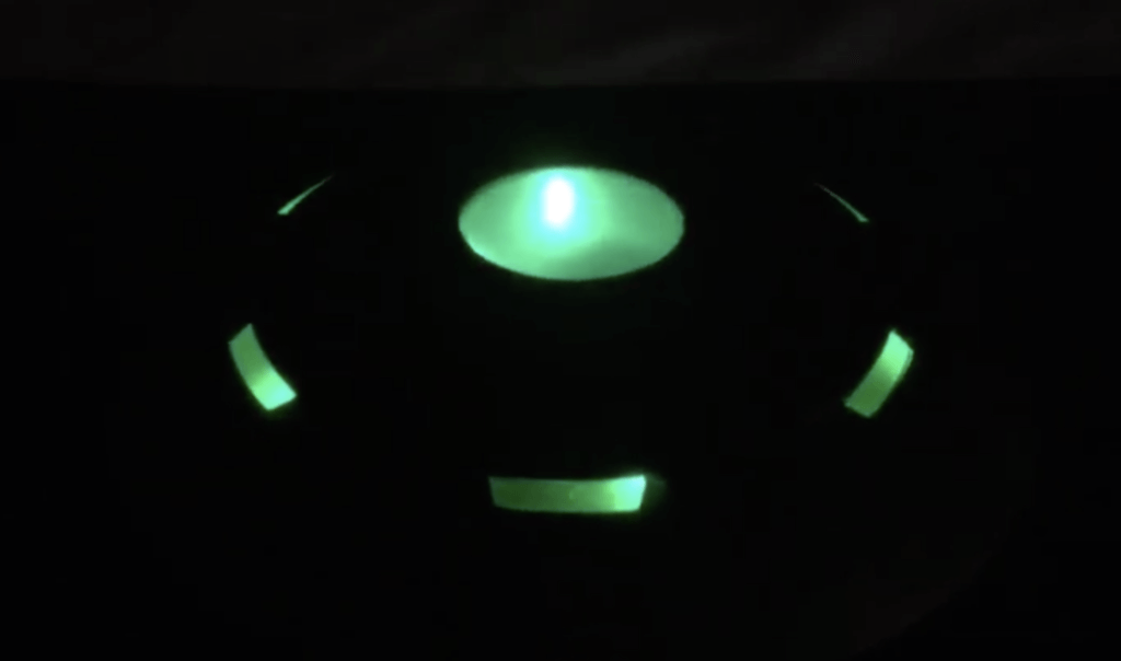
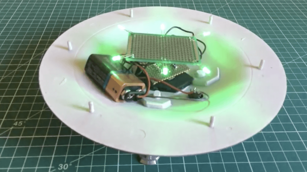
As you can see from the pictures and videos, the Arduino Nano controls the fade in/fade out behavior of six 3mm high intensity green LEDs.
The UFOs windows are green polystyrene and the whole effect gives it an eerie appeal!

What was your biggest struggle as you worked through this project?
Getting the code to work. Although a simple program, I am NO coder!
Did the project end up as you expected?
Exactly as I wanted it to be, although the connections from the Nano board to some stripboard containing the resistors turned out to be very “fiddly” in what was a confined space.
Looking back on this project, what can you say you have learned about programming and/or electronics through the creation process?
I have already some experience with electronics. My challenge was learning the programming.
What type of Arduino board, Arduino clone, or Arduino compatible board does your project use?
Arduino Nano
What components are used in your project?
Resistors, LEDs, stripboard
How do you power your project?
9 Volt Battery
Arduino Code:
int led1 = 3; // the PWM pin the first LED is attached to
int led2 = 5; // the PWM pin the second LED is attached to
int led3 = 6; // the PWM pin the third LED is attached to
int led4 = 9; // the PWM pin the fourth LED is attached to
int led5 = 10; // the PWM pin the fifth LED is attached to
int led6 = 11; // the PWM pin the sixth LED is attached to
int brightness = 0; // how bright the LEDs are
int fadeAmount = 5; // how many points to fade the LEDs by

// the setup routine runs once when you press reset:


void setup() {
  // put your setup code here, to run once:
  // declare pins 3,5,6,9,10,11 to be outputs:
  pinMode(led1, OUTPUT);
  pinMode(led2, OUTPUT);
  pinMode(led3, OUTPUT);
  pinMode(led4, OUTPUT);
  pinMode(led5, OUTPUT);
  pinMode(led6, OUTPUT);
}

// the loop routine runs over and over again forever:
void loop() {
  // set the brightness of pins 3,5,6,9,10,11:
  analogWrite(led1, brightness);
  analogWrite(led2, brightness);
  analogWrite(led3, brightness);
  analogWrite(led4, brightness);
  analogWrite(led5, brightness);
  analogWrite(led6, brightness);

  // change the brightness for next time through the loop:
  brightness = brightness + fadeAmount;

  // reverse the direction of the fading at the ends of the fade:
  if (brightness <= 0 || brightness >= 255) {
    fadeAmount = -fadeAmount;
  }
  // wait for 30 milliseconds to see the dimming effect
  delay(30);
}
 Stephen Dearden is a retired Chemist, has been an electronics hobbyist for over 30 years and enjoys building models. He is a self proclaimed total beginner to the world of programming.


