PetBit – an Arduino Fitbit for your hamster
Ever think about making an Arduino Fitbit? What about a PetBit – you know, an Arduino Fitbit for a hamster?
Speaking of hamsters…
Who doesn’t have a memory tucked away somewhere of a hamster going round ‘n round? And where are your records of that rotating? What, you mean you didn’t record it?! How do you know if your hamster set a PR or not?
Maybe you could have used PetBit – an odometer for a hamster wheel using an ESP8266.
Christopher Cooper, a member of Programming Electronics Academy, created PetBit for his niece and as a project to try out some new programming skills.
Checkout PetBit below and read Christopher’s great post on this project – I think you’ll be impressed!
Why the heck did you build a petBit?
For me to learn, I need to have a purpose. So when I have a mad idea, if it gives me a spark, then it gives me the purpose and I learn more, otherwise I end up just tinkering.
How does your project work?
- The main microprocessor is an ESP8266, which I selected for a few reasons.
- I wanted to see the differences between an ESP and Arduino
- Physical size
- Processor speed
- Power usage, as I knew the unit would be powered by battery
Although the sketch is fairly long, that is only because of the different screens being displayed on the TFT panel.
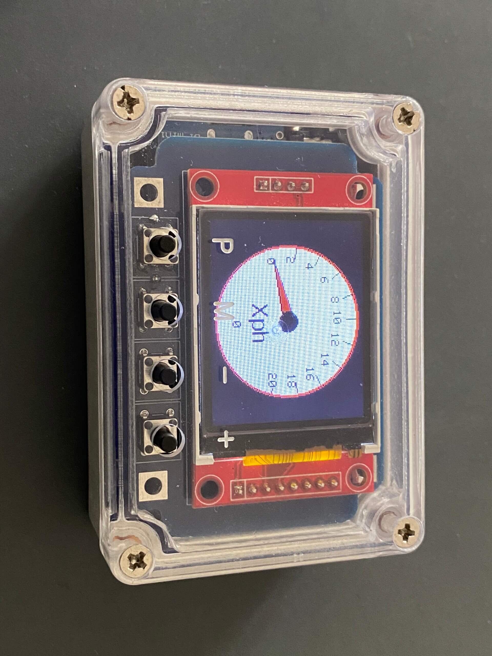
The unit has a single sensor, which is a reed switch, connected by a 3.5mm jack plug. The reed switch is positioned next to the hamster’s wheel and when the magnet passes by, the unit records the event accordingly. This data is then used to update the screens, such as:
- Odometer
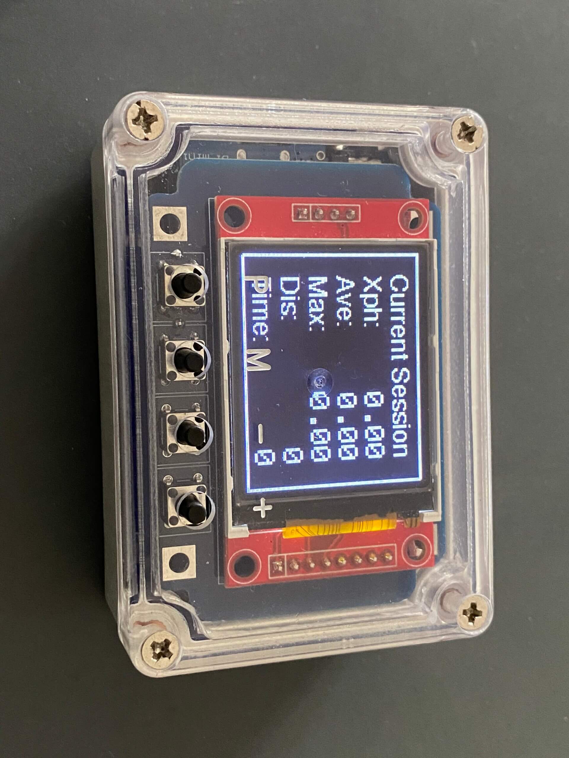
- Current session
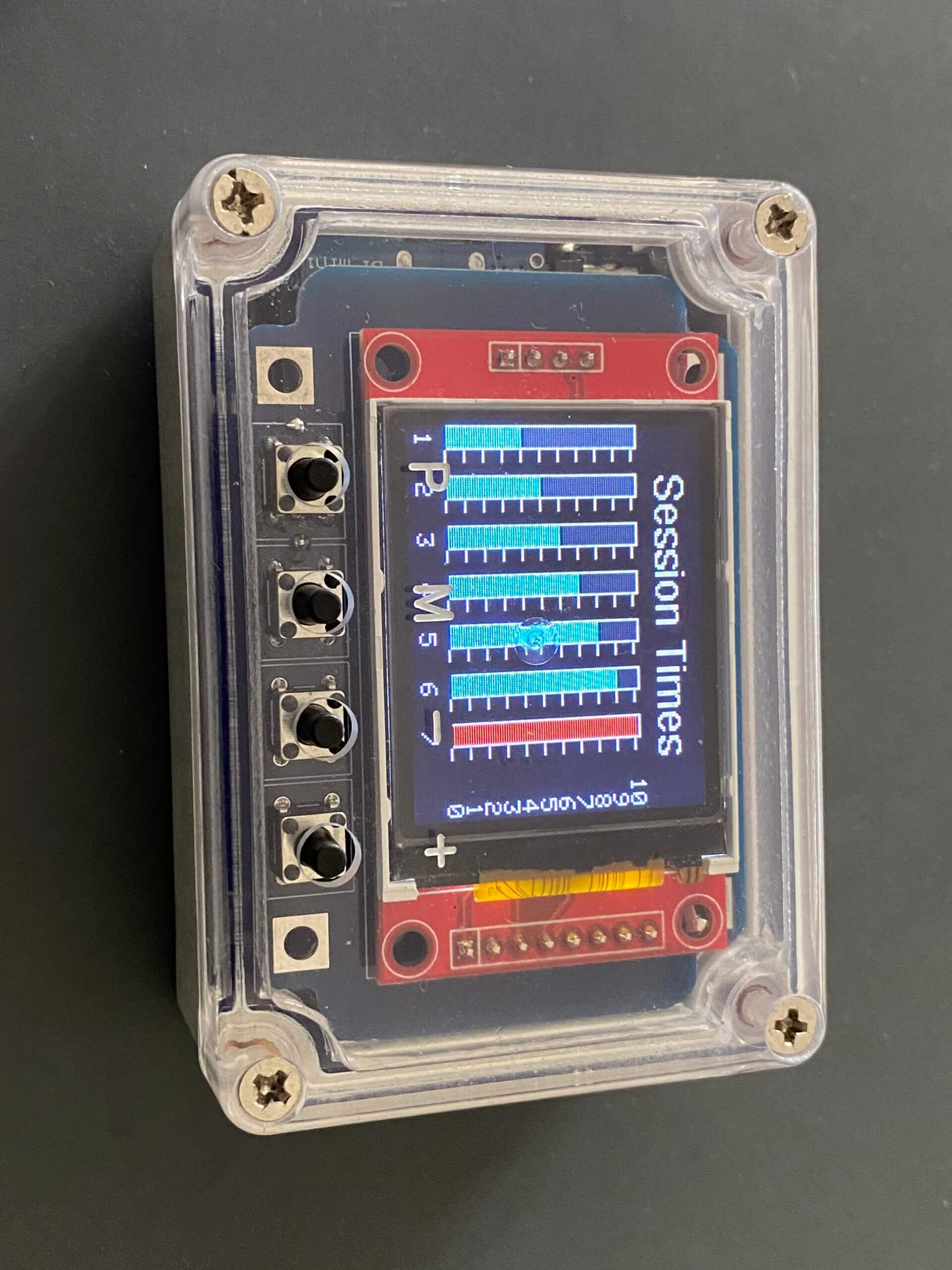
- Last seven sessions – time
- Last seven sessions – distance
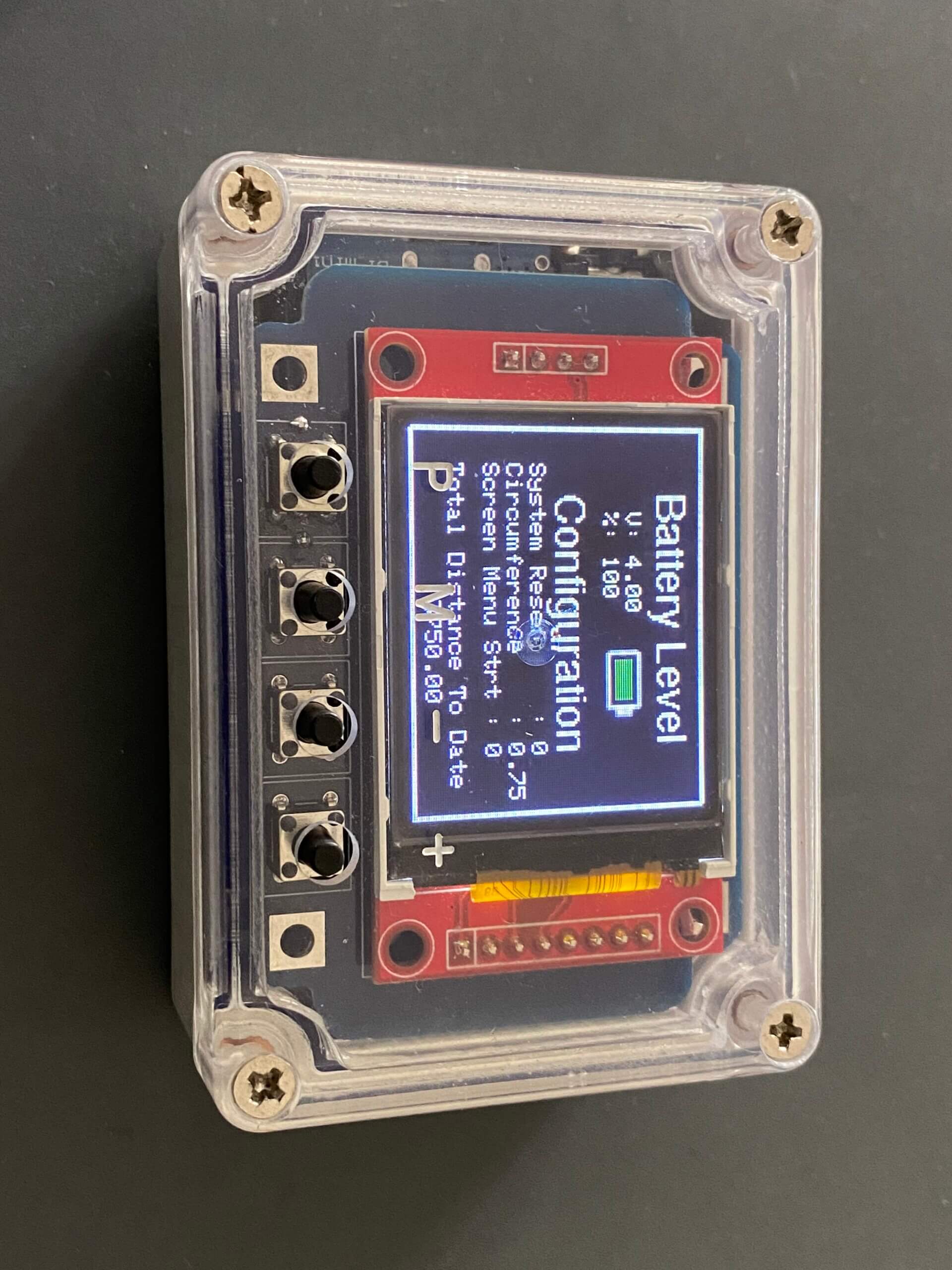
The user has the ability to set the wheel circumference, as well as the start screen when the unit is physically powered on. There is a master reset and the choice to load demo data.
Using the EEPROM within the ESP8266, I also record the total distance travelled since the start, as well as the last seven sessions, so should the battery fail, the data is not lost.
Other elements of the device are a D1 Mini battery charging shield, which I have linked to the ESP8266 via a voltage divider and the analog input. The voltage divider includes a potentiometer, so the reading of the battery can be accurately calibrated during construction.
I have now started a full stack development course, so one of my plans is to use the onboard wireless of the ESP8266 and link it to a website.
What was your biggest struggle as you worked through this project?
The project was great at forcing me to learn and it was like going back to school. I had two struggles, which really challenged me, simply because I haven’t had to use these skills since school, which was a long time ago!
To begin with, when programming the displays, knowing X & Y positions so I could plot the graphs and odometer readings was very difficult. I cheated somewhat by using code kindly provided by Kris Kitzpatrick, but even so, I needed to edit it heavily to make it all work.
The second challenge which was equally as difficult for me, was calculating time and distance travelled, and making sure the sketch worked properly, which could only be achieved by using Interrupts. Believe me, it was Programming Electronics Academy videos on Interrupts which made me realize from the start that I would have to use them.
Did the PetBit project end up as you expected?
No, better. The fun I had designing the start screen, playing with images, building the configuration screen, battery levels and the four actual data displays was super. I actually had to stop myself, as each time I picked up the project, I kept wanting to add more and more in.
Looking back on this project, what can you say you have learned about programming and/or electronics through the creation process?
Start with a clear design in your mind and then map it out on paper. Realize the project is multi leveled and you can’t work on everything, so split it up, such as:
- Main purpose
- Sensor
- Display
- Configuration
- Power
- Physical build
Once you have most areas sorted, ensure you build a prototype as the power and physical build/housing can be dealt with at the end.
Was the training at Programming Electronics Academy able to help you build your skill?
This is my second project and without Programming Electronics Academy, I would not have known where to start. I often return to [the training] videos as a reminder as they are invaluable.
Final Thoughts
Thanks to Programming Electronics Academy once again. Without [these courses], I would not be making such projects. Thanks to Kris Kasprzak for his graphing code, which made the displays much easier, although still very difficult!
Arduino Code:
About Christopher
 Christopher is the director of an IT company in the UK. He has recently picked back up his childhood joy of electronics, and taken on the exciting challenge of learning software development.


Wonderful fun!
I sent this to my son who is considering the new fad among the techs with pets in California: cat wheels.
PetBit – Cat Wheel edition? 😉