DIY Hydroponics Garden w/Arduino and IoT
Build your own custom rotating DIY Arduino hydroponics garden using IoT app Blynk
In this video lesson we will walkthrough creating an automated DIY Arduino hydroponics garden that utilizes our programming skills and an Internet of Things (IoT) App called Blynk.
Why, you ask? Because hydroponics is super cool, tasty food is nice to have, and through making this project we will demonstrate many potential uses of Arduino. Hopefully this walkthrough will give you some skills, and more importantly some inspiration, to create dozens of other cool IoT projects powered by Arduino.
[fvplayer id=”3″]
Hold on, what the heck is an Arduino? A sub sandwich? And who is this IoT lady? If you’re asking yourself these questions, have no fear! We have some great videos on our YouTube channel that introduce what Arduino is and its many uses, so check them out!
Here’s a table of contents to help you navigate this post:
- What is hydroponics?
- Why build a DIY hydroponics garden?
- Defining the problem
- System components overview
- Schematics and planning
- Getting the pump working
- Adding rotation
- Measuring the liquid level
- Connecting to our IoT App Blynk
- Putting it all together
- Resources
If you’re unfamiliar with the term Internet of Things (IoT), we also have a great IoT course for our members at Programming Electronics Academy that teaches all the essentials to get your projects up and running and connected to the cloud.
And this is just the tip of the iceberg! We’ve got 8 courses (and counting!) which cover everything from electronics fundamentals all the way to using LCDs and Servos in your projects.
If this is your first dip into the world of making and prototyping, welcome aboard! We’re so happy for you to have discovered this rich, intriguing world! You’re in the right place to start your Arduino adventures.
What is hydroponics?
So what is hydroponics anyway? Hydroponics is a method of growing plants without soil by using an aqueous water-based nutrient solution instead. There are many different subsets types of hydroponics, and they vary in how the nutrient solution is distributed to the plants, as well as how the nutrients are mixed into the water.

Aeroponics, for example, is the method of “misting” the plant roots with fine drops of the nutrient, usually on a timed schedule. For our DIY Arduino hydroponics garden, we’re going to create a “drip system” that is similar to the popular TowerGarden. If you’re looking for an excellent product that requires no building of your own, definitely check out TowerGarden.com.
Hold on, what about aquaponics? Isn’t that the same thing as hydroponics? Not exactly. Aquaponics is the method of combining aquaculture (raising aquatic animals such as fish) and hydroponics. Essentially, you use fish poop to add the required nutrients to your water solution and then you distribute that water to the plants, and then you utilize any of the nutrient distribution methods as previously mentioned.

Why build it?
Why should you build this Arduino Hydroponic Garden? Well, like we said before, we hope it will show you how cool Arduino is, and hopefully give you the inspiration and confidence to build many more projects other than just this garden. other microcontroller projects.
Additionally, But more than just that…growing your own food is:
- Fun (and easy! Adding the Arduino to the traditional hydroponic set-up helps automate the process, so even the most unskilled gardeners can find success)
- Tastes great
- You know exactly what’s going into your plants
- Hydroponic gardens don’t require weeding and there’s no messy soil involved.
- Allows you to grow vertically, taking up less space (so even people in small apartments or who don’t have backyards of their own can grow)
- Allows you to grow your favorite produce anywhere at anytime of year (I even grew these vegetables in England in the middle of winter – during weeks of freezing temps with no sun!)
- Uses up to 90% less water than traditional growing methods … although your power bill will be higher, so we’re definitely not arguing it’s “more green” than using soil, that’s for someone else to argue!
Just a quick disclaimer, we normally go much more in depth when it comes to walkthroughs and lessons, but we were so excited about this video we wanted to get this content out relatively quickly.
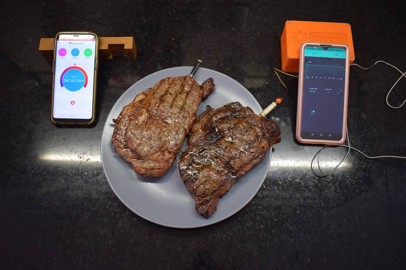
If you’d like to see a “full blown” PEA course on how we made this, similar to our IOT BBQ WIFI thermometer course, please let us know in the comments, and if there’s enough interest, we’ll go ahead and develop a multipart series that will dig much deeper into construction, code analysis, etc.
Another thing to note – we used a 3D printer to create our system, but you can definitely create a similar system from common materials available at your local hardware store. Check out this really excellent walkthrough from the “Over 60 Crafter” – we think this is one of the best DIY hydroponics available on YouTube – see below for a link to her video.
If you have a 3D printer, or have a friend that has one, or want to use a 3D printing service available online, you can access our STL files for free at Programming Electronics .com, see below for a direct link.

Defining the Problem
So how did this Arduino Hydroponic Garden get started anyway? We won’t mention names, but SOMEONE who happens to be the spouse of one of our PEA staff members has tried many times to start a garden at home. While the attempts have been valiant, each and every time the garden resulted in a bed of death. This was usually caused by the spouse becoming very busy due to work commitments, and the plants would unfortunately be neglected and not watered regularly. We’re talking many MANY gardens of despair.

So the spouse teamed up with the husband come up with a solution where the watering is automated, and could be monitored from afar. Thus was born the idea for the Programming Electronics Academy garden, or the PEEEEA Garden… Well it’s a working title, if you can think of something more witty, please let us know in the comments.
To recap, this DIY Arduino Hydroponic garden has to be…
- Automated, i.e. self watering
- Monitored from a far, i.e. the nutrient level in the reservoir has to be monitored via the internet in case the system starts running low on nutrient solution.
The initial iteration was left next to a window for two weeks and the side that was away from direct sunlight ended up dying, and the side closest to the window thrived, so the second iteration incorporates rotation, thus ensuring all the plants received equal amounts of sunlight.
Arduino Hydroponic Garden: System Components
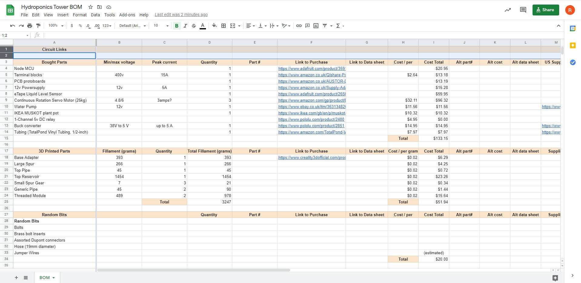
Let’s review the various components of the system. See below for a link to the Bill of Materials which will provide links for all the components for our DIY hydroponics garden:
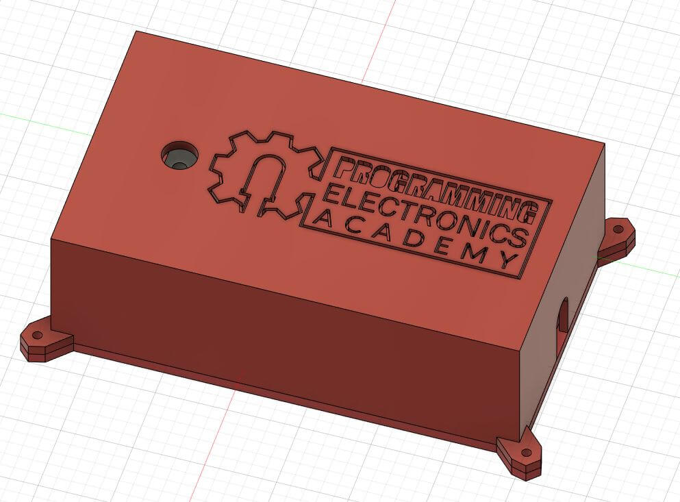
The links for the 3D models of the main assembly, the enclosure , and the associated STL files are located at the bottom of the post.
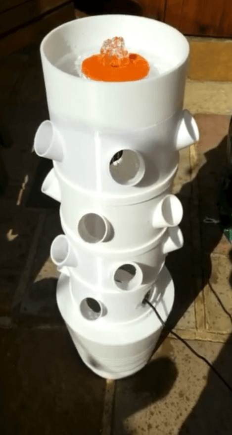
At the very bottom, you can see we have a reservoir which holds about 2 gallons of nutrient solution. We bought this one from Ikea for about 20 bucks, but a regular old bucket would work as well.
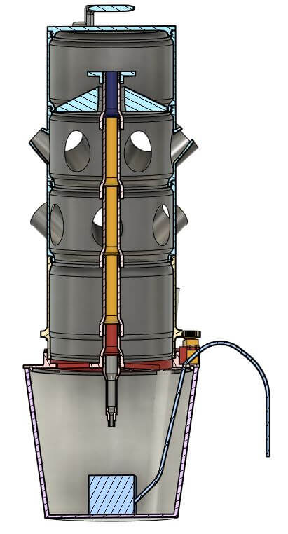
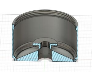
Next, you can see how the system interfaces with the reservoir, we call this red part the “base adapter”. Here you can see there’s a small gap between it and the parts sitting above it. This gap needs to be just right so that the top piece can rotate freely. Someday we might add some ball bearings here, but for right now, it seems to do the job.
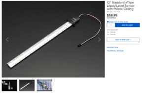
While we’re looking at the base adapter, you can see the water level sensor. We got this from an online electronics retailer called Adafruit.com, the product is called a “12 inch Standard eTape Liquid Level Sensor.” This allows us to measure how much nutrient solution is left in the reservoir.
Also here you can see the water pump, the three servos, three gears allowing the servos to couple to the main system, and a flexible pipe that connects the pump to the rest of the system.
A note on the servos. Yes, the easiest solution (and least complicated) is adding some grow lights that surround the garden. We were trying to avoid this option so we could reduce the electrical bill and harness the power of the sun. In the end, we ended up buying two grow lights as the sunlight available in the UK winter was just not enough.
The rotation does make it snazzier, so if you live in a region that has plenty of sunshine, this solution may work just fine for you. Also, 3 servos may seem like overkill, but we found this worked best versus one extra powerful servo. Mileage may vary for your garden!
Next is the large extended spur gear. This is the first of the large pieces that rotate, and the large gear is what interfaces with the 3 smaller gears attached to the servos. Notice that the top of the part is threaded. This is how it connects to all the parts above it. This makes it modular, so that you can add or subtract as many levels as you want.
Next is the threaded module. Add as many levels as you like. Each module contains 6 spots for 2 inch net cups.

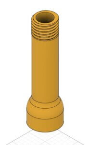
From this view we can also see the stationary pipe that’s in the center. The pipe, the base adapter, and the distributor at the top of the pipe do not rotate. The modules and top reservoir rotate around the stationary pipe.
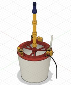
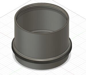
That leads us to the top reservoir. The purpose of this is to collect the nutrient solution and allow for even distribution on all sides of the system via these small holes. It has a top lid, and a handle to make it easier to transport.
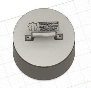
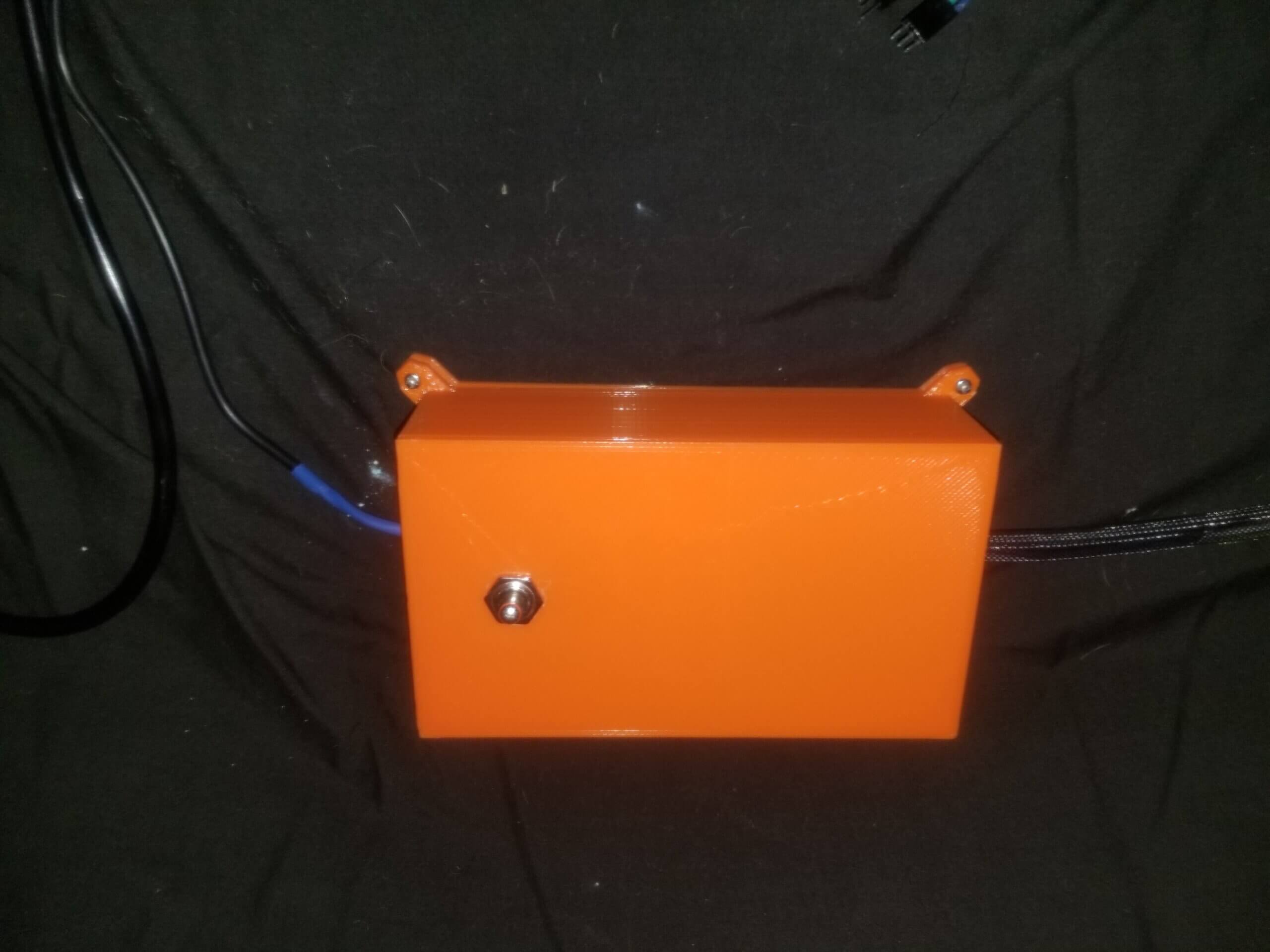
Last but certainly not least is the brains of our operation. Here you’ll see our enclosure with a power supply going in on one end, and the other end are the wires that power and control the servos, the water pump, and the water level sensor.
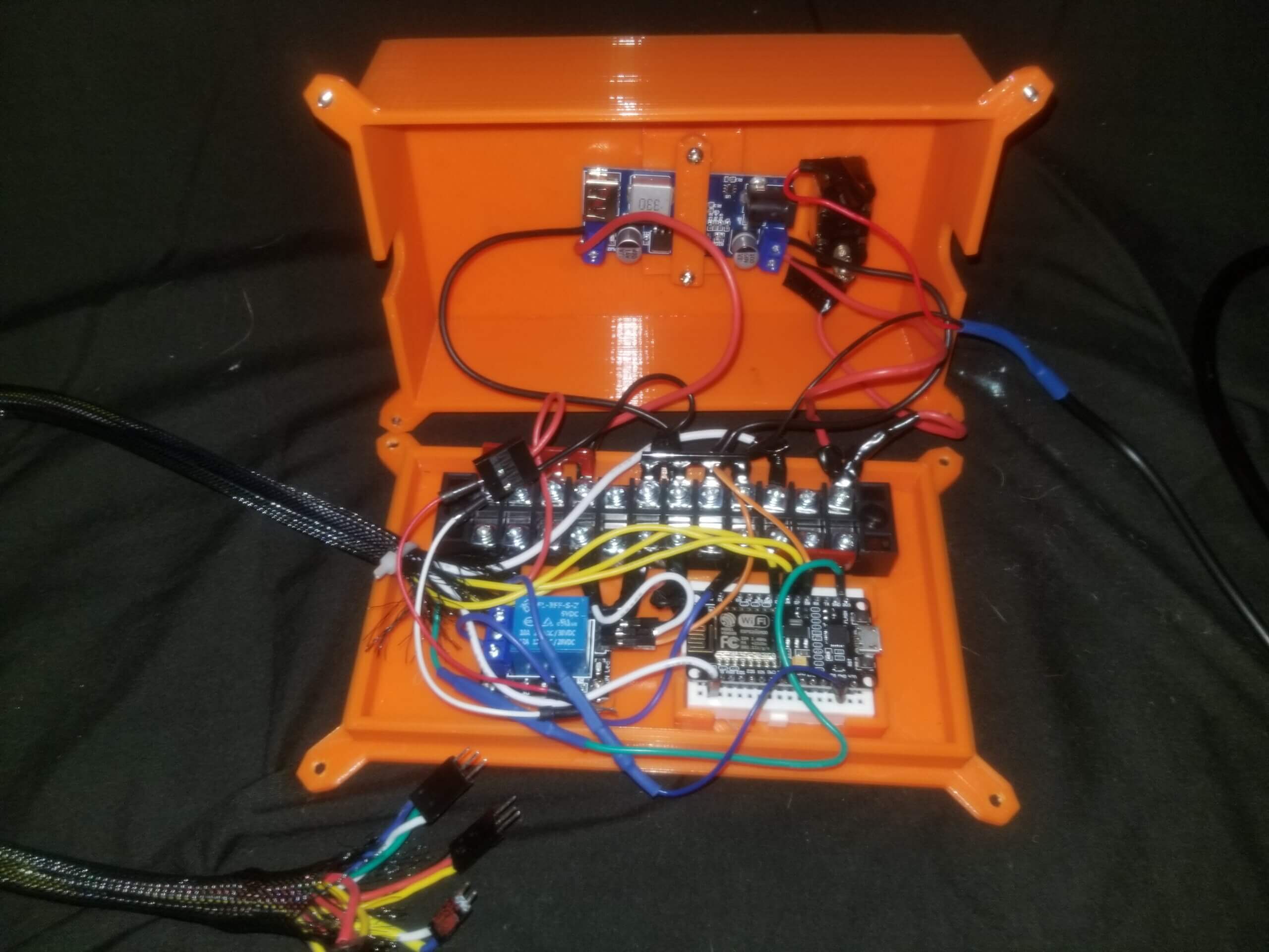
Inside the enclosure we have the microcontroller that powers this Arduino Hydroponic garden. We went with the ESP8266 NodeMCU due to its low cost and ease of use. You could just as easily use another board that’s compatible with the Arduino IDE. The power supply takes 100 – 240V AC power from the wall (230 in our case) and converts it to 12V DC.
The water pump operates at 12v, and we have a relay that allows our microcontroller to signal it on and off. We also have a buck converter that steps down the voltage from 12v to 5v to power the microcontroller and the servos. Here you’ll see a simple on / off switch, allowing us to control power to the system.
Lastly, you’ll notice that we’ve got a beefy terminal block in the enclosure. Since the pump will be drawing a substantial amount of current, we want to make sure the electrical connections and wires we are using can handle it. That’s all of the components for the PEEEA Garden.
If you’re savvy with hydroponics you might be wondering why we didn’t include a Parts Per Million (PPM) sensor or a pH sensor. While admittedly it would be cool to monitor this remotely, we discovered that they were not necessary for the final project. As long as you check the PPM and pH when you make a new batch of solution, the pH and PPM does not drift enough to make a difference in between solution swap outs. At first we were swapping solutions out every 7 days, but as our plants got larger and thirstier, we were having to swap out solutions every 4-5 days or so.
Arduino Hydroponics Garden: Schematics and Planning
The wiring of the “brain” is a bit complex simply to the number of total wires in the project, but generally it follows this schematic.
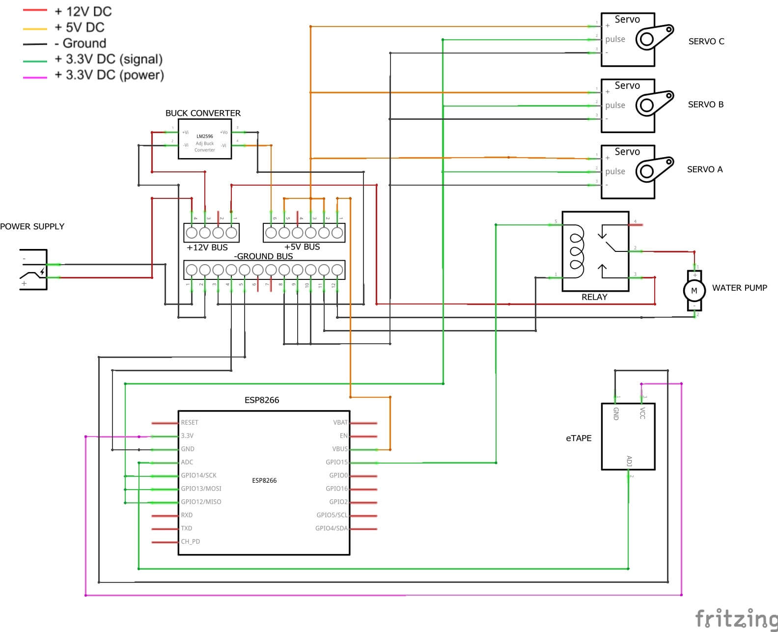
Now this is the final solution, we’re going to work bit by bit, and eventually we’ll end up with this solution. First, though, we’ll write a high level algorithm that goes over the main functions that we want our project to accomplish.
Our four main objectives are:
- Turning the water pump on and off for a specified amount of time
- Periodically rotating the garden ⅙ of a rotation
- Sending the water level to our app
- Making some setting adjustable from our app like pump running time
Seems pretty easy when we lay it out like that, and to be honest, from a coding perspective it IS a pretty straight forward problem, if you know how to program with Arduino. Likely the hardest part of this project will simply be constructing the apparatus in the first place.
We’re going to start tackling this algorithm by using the “lowest hanging fruit” mentality – that is, we are going to solve the easiest problem first, and try to build some “momentum” in our project creation process.
The easiest thing here will be turning the pump on, allowing it to run for a set amount of time, turn it off, let it rest for a set amount of time, and then repeat the cycle. Next we’ll get the servos operating and the garden rotating.
After that we’ll get the water level data sent to our app. This will involve connecting our microcontroller to the wifi, reading our sensor, then sending that data to our app. Lastly, we’ll combine all three and make it so you can adjust some of the settings via the app, so if you want to make small tweaks you don’t have to upload new code every time.
Getting the Pump Working
So let’s take a crack at function 1 – turn on the pump. We will do this using a relay. If you’re not familiar with relays, they basically are an electromagnetic switch that is operated by a relatively small electric current that can turn on or off a much larger electric current.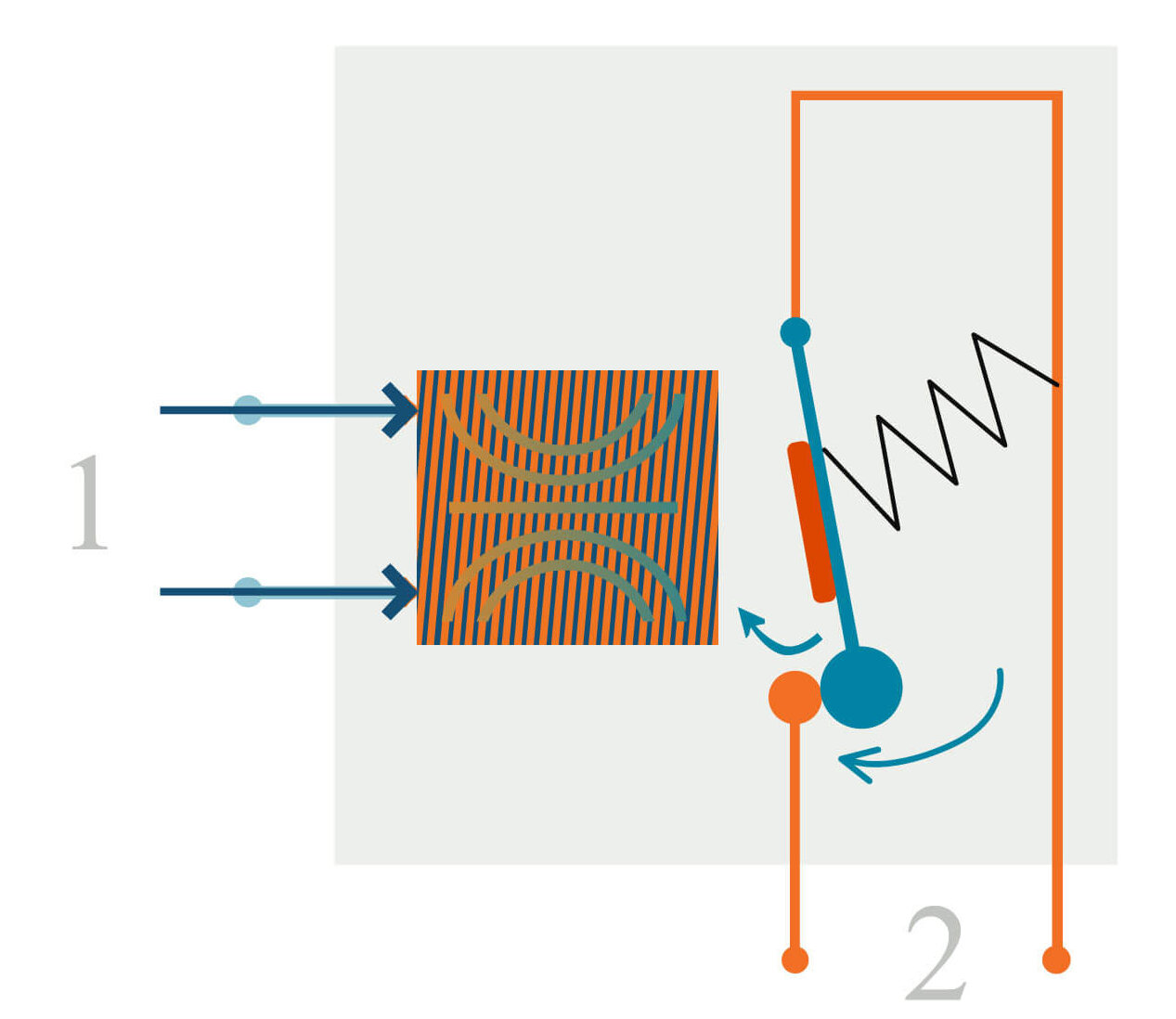
So we need to send a small amount of current to our relay, at which point it will activate and close the circuit between our pump and the power supply, and the pump will then turn on. Let’s do this via the digitalWrite command from our microcontroller.
If we tell the ESP8266 to make a pin HIGH, the relay then closes the switch, and our pump turns on. We wait a predetermined amount of time, and then make the same pin LOW, the switch opens again, and our pump turns off. Easy! The Arduino Hydroponic garden is alive.
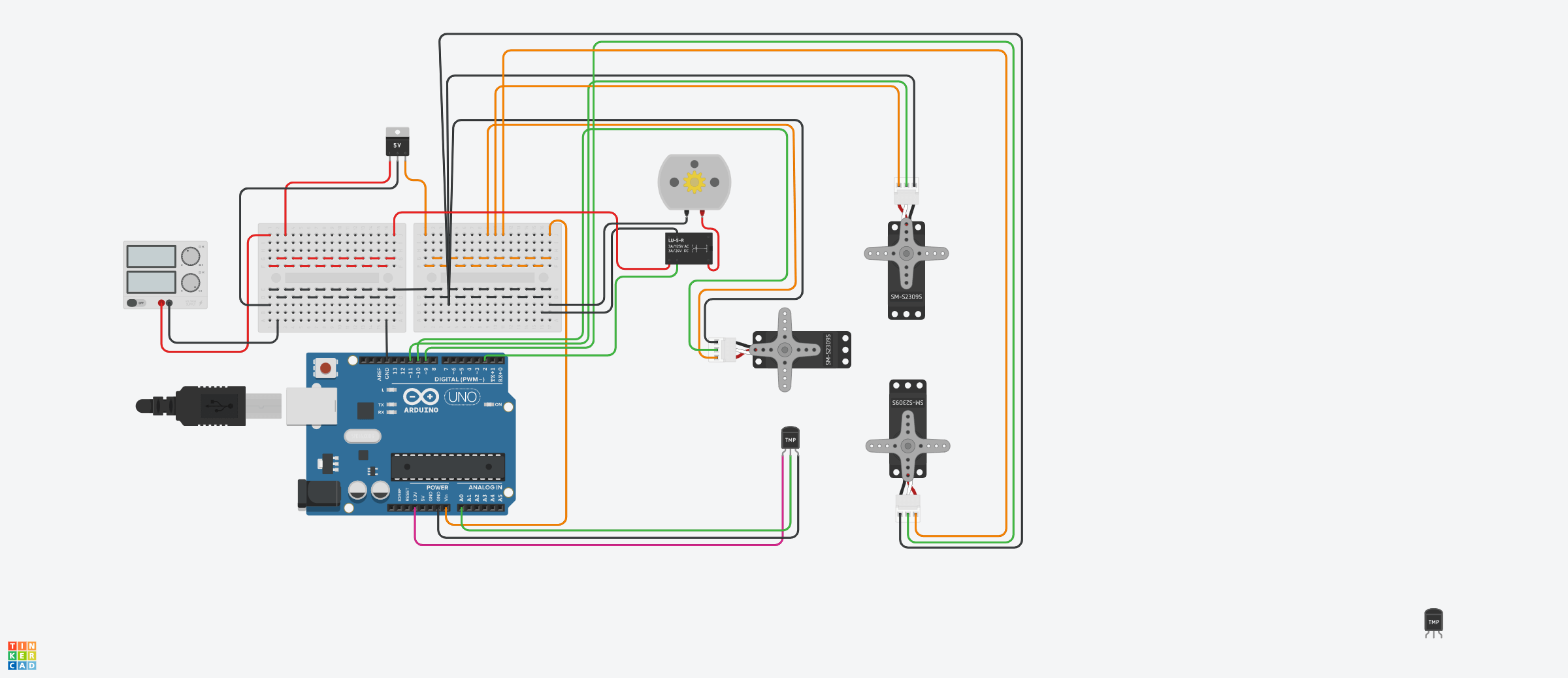
One method that is very helpful when prototyping is to build the experimental circuit in TinkerCAD and see if it works there, and if so, then build it in the real world. If you are unfamiliar with TinkerCAD, we have a great video detailing the features of it. So let’s take a look at the circuit we’ve created in TinkerCAD.
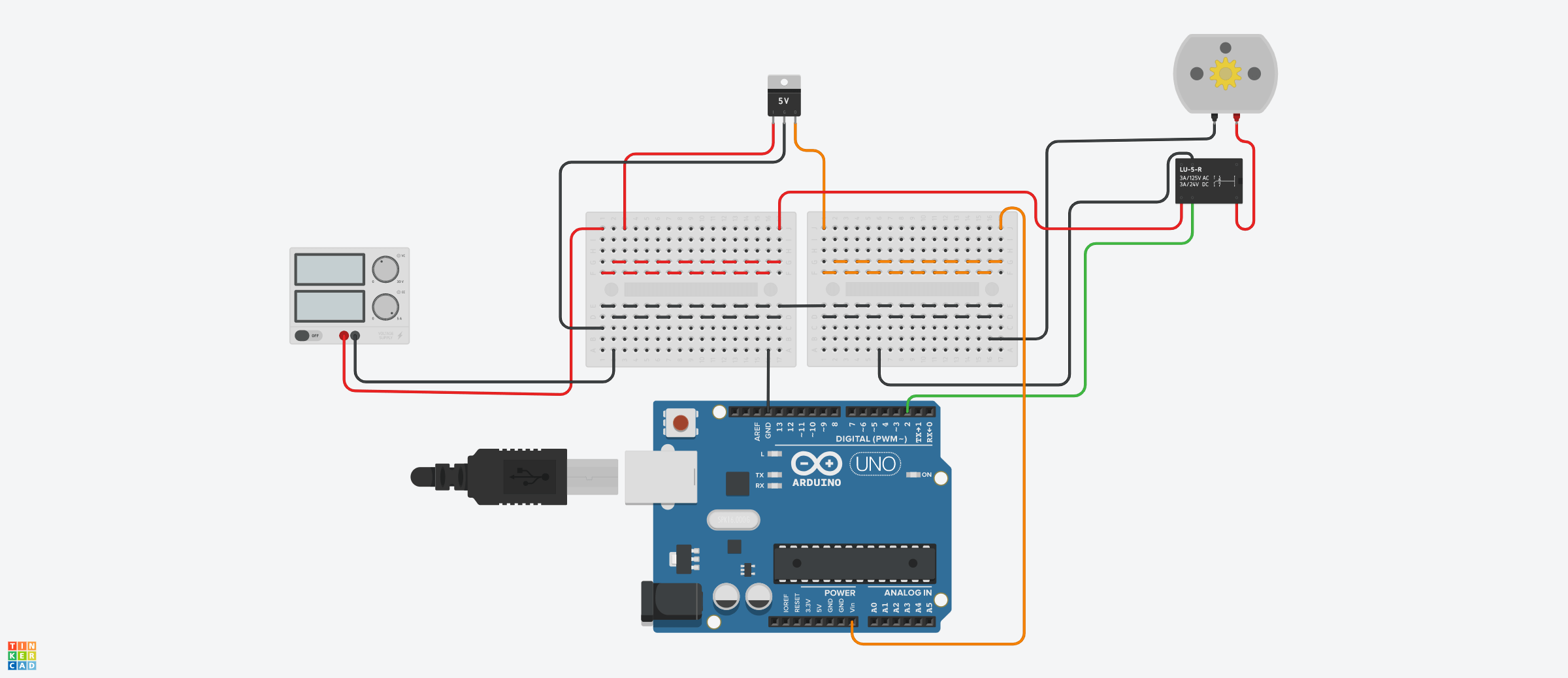
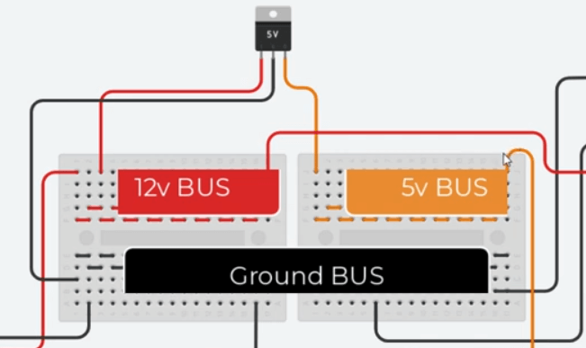
Our power supply takes 220VAC from the wall and converts it to 12v DC, up to 6amps, which is represented by the TinkerCAD bench power supply. From there we connect to our terminal block. You can see we’ve got the 12V “power bus” represented by the red wired breadboard.
The ground bus is represented by the lower half of both these breadboards, and is wired so that anything connected here will be in parallel. Finally, this LM7805 5V regulator here, represents our buck converter, and as you can see, it has 12V coming in, and 5V going out, which is connected to the 5V power bus.
Generally speaking, the 12V bus will power the pump, and the 5V will power everything else, including the ESP8266. For the purposes of testing our circuit, we’ll use an Arduino Uno because TinkerCAD does not have any ESP8266 microcontrollers available. It should work the same, but we just need to keep in mind that the ESP8266 uses 3.3v logic, and the Uno uses 5v.
The motor represents our pump, and when it’s running, we can assume our pump would be running instead. Finally, we have our relay. You can see the high voltage circuit here, the red 12V wire from the 12V bus goes into the circuit, then comes back out, and into the motor.
This is the circuit that is open, or not active. When we write digital pin 2 HIGH, this sends 3.3V (because it’s an ESP8266 in real life, not an Uno) to the relay, which energizes the magnetic coil, this closes the relay switch, and the pump turns on. When pin 2 goes LOW, the switch opens, the pump stops.
If you have a coding background, you can probably guess the required code is going to be extremely simple. Let’s take a look at it.
unsigned long pumpOnTime = 15 * 60 * 1000; // how long pump runs in milliseconds
unsigned long pumpOffTime = 15 * 60 * 1000; // how long pump "rests" in milliseconds

const byte relayPin = 2; // the pin our relay is attached to

void setup() {

pinMode(relayPin, OUTPUT); // set our relay pinmode to output

}

void loop() {

digitalWrite(relayPin, HIGH); // Pump ON
delay(pumpOnTime); // delay for pump run time
digitalWrite(relayPin, LOW); // Pump OFF
delay(pumpOffTime); // delay for pump "rest" time

}
Essentially what we’re doing in this sketch is no different than the first program most coders learn to create, which is blinking an LED on and off. Now if you’ve never coded anything in your life, this is going to look and sound pretty foreign, but I assure you with just a little background knowledge you can learn this relatively quickly. Do yourself a favor and take our “Arduino Course for Absolute Beginners” and the code in this Arduino Hydroponic garden will seem like child’s play.
Even if you’re unfamiliar with coding, stick with us, you’ll be able to understand the broad strokes of what we’re doing and it might persuade you to learn to code.
OK – pep talk over. Let’s go line by and line – First we declare two variables, our pumpOnTime and pumpOffTime. We’ve gone with 15 minutes for both, so to convert to milliseconds, we need to multiply 15 times 60 times 1000.
Feel free to modify these times, that’s just what we’ve found works best for our plants and is also what many websites recommend. For our TinekrCAD experiment, however, we’ll reduce this to just a few seconds so we can test it out and not have to wait so long.
Next we declare relayPin as 2, per our wiring diagram. In setup we’ll make that pinmode an output. In the loop, we turn on the pump, delay and let it run for our “pumpOnTime” variable duration, then we turn it off, then we let it “rest” or not run, for the duration of our “pumpOffTime” variable.
We verify the code, it checks out, then we copy and paste it into TinkerCAD, change the variables to 2000 milliseconds, or 2 seconds, and start the simulation and voila, it works as expected.
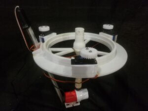
Here’s a video of the very first iteration of the garden and the first time we turned it on using this code.
Adding Rotation
Ok, next we’re going to get the garden rotating. Again, back to TinkerCAD so we can set up our experimental circuit. We’ll keep the relay and pump around, but let’s delete the wires so that things look a little less cluttered.

In the actual Arduino Hydroponic garden our servos are the “continuous rotation” type which allows them to spin continuously, either clockwise or counter clockwise. This is different from “standard” servos that are usually limited to 90 or 180 degrees of movement.
In TinkerCAD they don’t have 360 servos, so we’ll use the standard ones that they have, just realize the positions they go to is not what it will look like in real life. To move servos with an Arduino compatible board, we use the built in Servo Library. The write() function of the Servo library is what we’ll use for rotation.
For continuous servos, instead of telling them what position to go to, you tell them what speed and direction to rotate in. When 90 is written, the servo speed = 0. If 0 is written, the servo speed rotates at maximum speed in a counterclockwise direction. Lastly, when 180 is written, the server rotates at maximum speed in a clockwise direction.
For our purposes, we’ll write 120 which equates to about ⅓ max speed in a clockwise direction, and we’ll rotate this for about 3 seconds, which roughly equates to ⅙ total rotation for the garden. garden. This means every 6 full cycles the garden will have rotated 360 degrees. With everything correctly wired, let’s jump into the code.
#include <Servo.h>
Servo myServoA; // create instance of Servo named myServoA
Servo myServoB; // create instance of Servo named myServoB
Servo myServoC; // create instance of Servo named myServoC

int servoSpeed = 120; // 0 = CCW full speed | 90 = zero speed | 180 = CW full speed
unsigned long rotationTime = 3.3 * 1000; // how long servos run per cycle

const byte servoPinA = 11;
const byte servoPinB = 10;
const byte servoPinC = 9;


void setup() {

  myServoA.attach(servoPinA); // correlate instance of Servo with pin
  myServoB.attach(servoPinB); // correlate instance of Servo with pin
  myServoC.attach(servoPinC); // correlate instance of Servo with pin

}

void loop() {

  myServoA.write(servoSpeed); // set servo to servoSpeed
  myServoB.write(servoSpeed); // set servo to servoSpeed
  myServoC.write(servoSpeed); // set servo to servoSpeed

  delay(rotationTime);

  myServoA.write(90); // set servo to "off"
  myServoB.write(90); // set servo to "off"
  myServoC.write(90); // set servo to "off"

  delay(5000); //delay for 5 sec while servos are "off"

}
If any of this is unfamiliar to you, we have an excellent servo course that will teach you the fundamentals of using servos with Arduino.
So first we include the servo library. Next we create instances of the Servo class called myServoA, myServoB, and myServoC. Next we’ll declare a few variables, first we’ll define that speed we talked about before. We also will define the rotationTime.
Again, these two can be tweaked to get the right amount of rotation, we recommend turning the garden a fraction of the total number of openings you have per module. We have 6, so we’re going to turn it ⅙ of a full revolution, or about 60 degrees.
Next we’ll define the pins where the servo signal wires are attached. In setup we’ll attach each of the servo instances to a pin. Down in the loop, we’ll start off writing a servo speed to each of the servos. Then we delay for the defined rotation time.
Lastly we’ll turn the servos “off” by writing 90. We added a delay of 5 seconds so you can appreciate the end of a cycle. Ok, lets copy the code, put it in TinkerCAD and hit start simulation. Great, looks like it works.
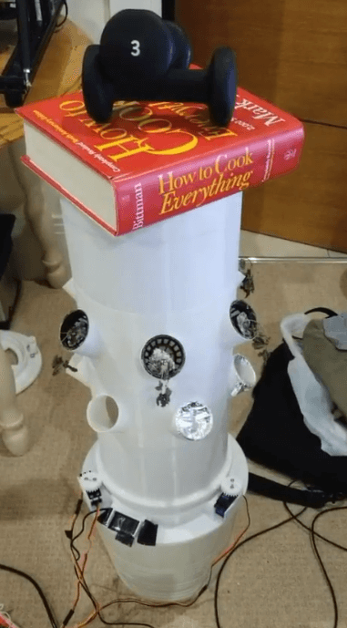
Next we’ll build the Arduino Hydroponic garden in the real world. Here’s a video of a test we ran with 20 lbs of weight on top of the garden to simulate the massive plants we would be growing in the near future. We simulated it running for 3 months by reducing the duty Cycle, and ran it overnight. Thankfully, even under load, it held up!
Measuring the Liquid Level
Ok we’re making some serious progress here! Next let’s see if we can get the water level sensor working. Our eTape Liquid Level Sensor has one pin for power, either 3v or 5v will work, one pin for ground, and on the third pin we can measure voltage and relate it to the amount of liquid remaining in our reservoir.
It’s got a prebuilt voltage divider on board, so we know the output voltage we’ll be measuring will be somewhere between 0V and 1V.
We also know that this voltage varies linearly with the amount of water it’s measuring, so to keep things very simple, we’ll measure the voltage when the reservoir is full, and we’ll take another measurement when the reservoir is just about empty, when the water level is JUST above the top of the water pump.
We’ll call these two variables “lowEtapeValue” and “highEtapeValue”. Then we’ll use the map function to calibrate an output that makes sense.
If you’re getting a little lost here, check out our IoT course for more information regarding voltage dividers, and our Arduino Basics course to find out more about the MAP function, both are available at Programming Electronics .com.
So let’s see how we can emulate this aspect of our Arduino Hydroponics garden at TinkerCAD. Well our eTape is not available as a part, but we could use a temperature sensor as a substitute to check our code and wiring.
As you can see, you can adjust the temperature the sensor is exposed to, which changes what voltage is sent to the microcontroller, so it will replicate our eTape quite nicely.
Let’s take a look at the code:
int rawLiquidReading; //declare our raw data variable in integer form
float liquidLevel; // declare our calculated liquid level, which will be a percentage
const long lowEtapeValue = 590; // this variable corresponds to the reading of the sensor when the reservoir is nearly empty
const long highEtapeValue = 740;  // this variable corresponds to the reading of the sensor when the reservoir is full

const byte liquidLevelPin = A0; //the pin our eTape is connected to

void setup() {

  pinMode(liquidLevelPin, INPUT); // declares the pin our Etape is connected to as something to read

  Serial.begin(9600); // begin serial communication

}

void loop() {


  rawLiquidReading = analogRead(liquidLevelPin); // read the pin, expecting readings between 0 - 1023
  Serial.print("Raw Liquid Level: ");
  Serial.print(rawLiquidReading); // display raw reading

  liquidLevel = map(rawLiquidReading, lowEtapeValue, highEtapeValue, 0, 100); // converts our raw reading into a percentage
  Serial.print(" / Liquid Remaining: ");
  Serial.print(liquidLevel);
  Serial.println("%."); // display the percentage of the liquid remaining in the reservoir

}
You’ll see how this is done once we jump over to TinkerCAD. Let’s copy and paste this code into TinkerCAD and see what happens….So after some trial and error I can tell you those readings for “lowEtapeValue” and “highEtapeValue” are accurate for the reservoir we chose, but you’ll need to do some experimentation to determine the correct values for your system.
As you can see, after we open the serial monitor, the raw data and the liquidLevel are printed. As we adjust the temperature at the sensor, the values go up and down.
But the liquidLevel is showing some negative values. It’s because the eTape values are set for the actual project.
So let’s see what the value is when the temperature is at the minimum… looks like 20. Now what about the maximum? Looks like 358. Let’s pop these values into the code and see what happens.
Now when we slide the temperature all the way down to the minimum, the liquidLevel shows 0%, and when we slide to the maximum, it shows 100%. Happy days. This is the exact technique you’ll need to apply to your own Arduino Hydroponics Garden to calibrate the liquid Level.
Arduino Hydroponics Garden: Adding some IoT Magic
The next part of this walkthrough is going to assume a bit of knowledge. First, that you are familiar with the Blynk app. If you’re not, check out our BBQ thermometer class, it goes super in depth into Blynk. You can find this course at Programming Electronics. com
The second is you’re familiar with the millis function. The millis function allows us to get rid of any delays in our code which would essentially jam up the connection between our device and the Blynk App. We want tight tight loops, otherwise Blynk fails. If you’re unfamiliar with millis, checkout our free millis mini course.
Now using the same wiring for the eTape, let’s revise the code:
// BLYNK STUFF //
#define BLYNK_PRINT Serial
#include <ESP8266WiFi.h>
#include <BlynkSimpleEsp8266.h>

char auth[] = "UNIQUE BLYNK AUTH TOKEN"; //Blynk Auth Token for "Water Level Test"
char ssid[] = "YOUR WIFI NETWORK";
char pass[] = "YOUR WIFI PASSWORD";
// END BLYNK STUFF //

//Misc variables
unsigned long previousTime = 0;
unsigned long sampleTime = 2000; // How often we're going to sample the water level


int rawLiquidReading; //declare our raw data variable in integer form
float liquidLevel; // declare our calculated liquid level, which will be a percentage
const long lowEtapeValue = 590; // this variable corresponds to the reading of the sensor when the reservoir is nearly empty
const long highEtapeValue = 740;  // this variable corresponds to the reading of the sensor when the reservoir is full

const byte liquidLevelPin = A0; //the pin our eTape is connected to

void setup() {

  pinMode(liquidLevelPin, INPUT); // declares the pin our Etape is connected to as something to read

  Serial.begin(9600); // begin serial communication

  Blynk.begin(auth, ssid, pass);

}

void loop() {

  unsigned long currentTime = millis();
  static unsigned long previousTime = currentTime;

  Blynk.run();

  if (currentTime - previousTime >= sampleTime) { // execute code below once sampleTime is exceeded

    rawLiquidReading = analogRead(liquidLevelPin); // read the pin, expecting readings between 0 - 1023
    Serial.print("Raw Liquid Level: ");
    Serial.print(rawLiquidReading); // display raw reading

    liquidLevel = map(rawLiquidReading, lowEtapeValue, highEtapeValue, 0, 100); // converts our raw reading into a percentage
    Serial.print(" / Liquid Remaining: ");
    Serial.print(liquidLevel);
    Serial.println("%."); // display the percentage of the liquid remaining in the reservoir

    Blynk.virtualWrite(V1, rawLiquidReading); //Push liquid level data to V1 in App
    Blynk.virtualWrite(V0, liquidLevel); //Push liquid level data to V0 in App

    previousTime = currentTime;

  }

}

// This function will be called every time the Stepper Widget in Blynk app writes values to the Virtual Pin 2
BLYNK_WRITE(V2)
{
  sampleTime = 1000 * param.asFloat(); // assigning incoming value from pin V2 to a variable, then convert to MS
  // You can also use:
  Serial.print("Sample Time is now: ");
  Serial.println(sampleTime);
}

BLYNK_CONNECTED()
{
  // Synchronizes values on connection
  Blynk.syncVirtual(V2);
}
So the goal here is to take what we already have to find the Liquid Level, and add IoT functionality to it by injecting some Blynk code.
First we include the required Blynk libraries, and then we also supply the unique authentication token which we get from the Blynk app. We also provide the WiFi network name as well as the password so our device can connect.
Previous time we’ll set to 0, and sampleTime, this is how often we want to push the data from eTape sensor to our app, let’s start at every 2 seconds.
The next new bit of code will be in setup where we add Blynk.begin(auth, ssid, pass), this function instructs our device to connect to the Blynk servers with our credentials. We put it in SETUP because we only need to connect once.
Next, in the loop, you’ll see that instead of using delay(sampleTime), we’re going to instead utilize the millis function. This allows us to keep running through the loop.
A delay would stop everything, and therefore our connection to the Blynk server would be severed. We set currentTime to millis, which means current time will always correspond to the internal stopwatch in the ESP8266.
It starts at zero, and goes for approximately 50 days, then starts back over at zero. Something to keep in mind if you’re going to leave your Arduino Hydroponics garden for more than 50 days!
Next is the Blynk.run function, which is required to maintain our connection to Blynk servers.
Next you’ll see an IF statement. If currentTime, let’s say 1000 milliseconds, minus previousTime (right now is zero) is greater than or equal to sampleTime, then it will run the code below. If not, it will skip down to the next bit of code.
Well in this case 1000 minus zero is 1000, and it does not exceed 2000, which is sample time. Therefore we’ll skip this if statement. But there’s nothing else in the loop, so we’ll start at the top of the loop again, and we hit Blynk.run again.
Perfect, that’s what we want, to maintain connection. If we delayed, it would be 2 seconds before Blynk.run was executed, and we’d have problems.
What happens when millis equals 2000? Well 2000 – 0 equals 2000, so our if statement is true, so we’ll execute the code. All of this should look familiar from when we initially set up the sensor. At the end, you’ll see three new lines. Blink.virtual Write, V1, raw liquidReading, then Blink.virtual Write, V2, liquid level, and then finally previousTime = currentTime.
When we execute virtual.Write, we’re pushing data to the virtual pin. On our blink app, we’ll add widgets that are setup to receive this data.
We’ve designated virtual pin V1 and V0, so when we make our app, we’ll need to remember to assign our displays to these pins.
Lastly, we have previousTime = currentTime. So after the first time through, previousTime will now equal 2000.
When we execute the loop again, and arrive at the IF statement this time, currentTime, we’ll say is 2500, and we subtract previous time, which is currently 2000, we get 500. Is 500 greater than or equal to our sampleTime of 2000? No, it’s not. So we continue running through the loop.
We’ve got two more bits of code at the bottom, which aren’t really necessary but I added them to help me do some troubleshooting.
We’ve got a function called BLINK_WRITE for Virtual Pin 2. When we change the value of V2 on the app, this data will be pushed to whatever we designate inside this function.
So on our app if we change the Value of V2, it will be pushed to the device, assigned to sampleTime, and converted to milliseconds.
This allows us to adjust the SampleTime or “refresh rate” on the fly.
Last, we’ve got Blynk Connected. This is executed only once, and when the device first connects to the Blynk App. Blink.syncVirtual ensures that before the code is executed, we sync our pins, therefore if we had V2 equal to 4, and the device connects, SampleTime will be assigned to 4000, instead of the default 2000 which we declared at the beginning of the sketch.
Before we test it out, let’s take a quick look at our Blynk App.
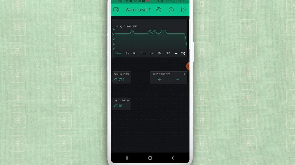
First we have a “super chart” widget. You can put all kinds of data streams into this guy, but for our purposes, we’re just going to display the Liquid Level percentage, which is virtual pin 0.
Next we have the Value Display widget for our raw liquid reading. This isn’t really necessary, but it’s nice to see what value is actually being read at A0. This will correspond to virtual pin 1.
Next, we’ve got another Value Display widget, this time Liquid Level. This should match exactly what’s on the chart, but again, nice to see data read out instead of just a line on a chart.
Last but not least we have a Step widget. This allows us to adjust the sampleTime, or refresh rate. You can adjust the step if you want to increase or decrease how much the value changes every time you hit the up or down button. We’ll leave this at 1. This corresponds to virtual pin 2.
That’s about it for the app. Let’s see this thing in action.
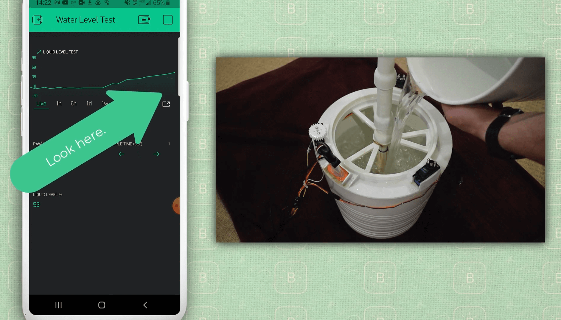
I asked my husband to pour water into the reservoir while I monitored the Blynk App and the serial monitor. And yes, we got water ALL OVER the rug… We definitely should have done this outside, but our laptop was dead so we had to connect to the PC in order to view the serial monitor…
Putting it all together to complete the Arduino Hydroponics Garden
Ok we’re just about there. The last thing we need to do is combine all these sections of our Arduino Hydroponics garden into one big sketch, and make sure they’re all compatible with Blynk. Remember that delay functions won’t work with Blynk, so that means we need to edit both the pump ON and OFF, as well as the servo code.
We’ll check out the new edits in the code, then we’ll check out the Blynk App, and then we’ll show this baby in all her glory.
Final Code:
#define BLYNK_PRINT Serial
#include <ESP8266WiFi.h>
#include <BlynkSimpleEsp8266.h>
#include <Servo.h>

// BLYNK STUFF //
char auth[] = "4KGHmPHdFEAIo2VPFwp-M5a9vba0xstT";
char ssid[] = "Schanda NET";
char pass[] = "35Stephanie";
// END BLYNK STUFF //

Servo myServoA;
Servo myServoB;
Servo myServoC;

// Adjustable variables to get from Blynk App, but declare them here
int servoSpeed = 130; // 0=CCW full speed, 90 = zero speed, 180 = CW full speed
unsigned long rotationTime = 3.3 * 1000; // how long servos run per cycle
unsigned long pumpOnTime = 15 * 60 * 1000; // how long pump runs
unsigned long pumpOffTime = 15 * 60 * 1000; //* 60 * 1000; // "rest" time

//Misc variables
unsigned long previousTime = 0;
String pumpState = "Off";

//Liquid level variables //
int rawLiquidReading;
float liquidLevel;
const long lowEtapeValue = 590;
const long highEtapeValue = 740;

// Pins Per the ESP8266 NodeMCU
const byte servoPinA = 14;
const byte servoPinB = 12;
const byte servoPinC = 13;
const byte liquidLevelPin = A0; //provides voltage between 0-1024, higher number = more resistance = more liquid
const byte relayPin = 15; //when relay turns on, 12v pump runs

void setup() {

  pinMode(liquidLevelPin, INPUT);
  pinMode(relayPin, OUTPUT);

  Serial.begin(9600);

  Blynk.begin(auth, ssid, pass);

}

void loop() {

  Blynk.run();

  unsigned long currentTime = millis();
  static unsigned long previousTime = currentTime; //previousTime = currentTime first time through loop, then ignored
  static byte state = 1; //assigns state = 1 first time through loop, then ignored

  /* There are 3 states:
      1 - ROTATE THEN STOP
      2 - PUMP RUN THEN OFF
      3 - TAKE LIQUID MEASUREMENT THEN "REST"
  */

  /**** BEGINNING STATE 1 - ROTATE THEN STOP****/

  if ((currentTime - previousTime >= rotationTime)  && (state == 1)) { // do once rotation time is exceeded
    servoStopThenDetach(); // turn off servos
    state = 2;
    previousTime = currentTime;
  }

  else if ( (state == 1) && (!myServoA.attached()) ) { // if servos aren't already attached, attach and activate them
    servoAttachThenRotate();
  }

  /**** END STATE 1 ****/

  /**** BEGINNING STATE 2 - PUMP RUN THEN OFF ****/

  if ((currentTime - previousTime >= pumpOnTime)  && (state == 2)) {
    digitalWrite(relayPin, LOW); // Pump Off
    pumpState = "Off";
    state = 3;
    previousTime = currentTime;
  }

  else if ( (state == 2) && (pumpState = "Off")) {
    digitalWrite(relayPin, HIGH); // Pump On
    pumpState = "On";
  }

  /**** END STATE 2 ****/
  /**** BEGINNING STATE 3 - TAKE LIQUID MEASUREMENT THEN "REST" ****/

  if ((currentTime - previousTime >= pumpOffTime)  && (state == 3)) {

    rawLiquidReading = analogRead(liquidLevelPin);
    Serial.print("Raw Liquid Level: ");
    Serial.print(rawLiquidReading);

    liquidLevel = map(rawLiquidReading, lowEtapeValue, highEtapeValue, 0, 100);
    Serial.print(" / Liquid Remaining: ");
    Serial.print(liquidLevel);
    Serial.println("%.");

    Blynk.virtualWrite(V5, rawLiquidReading); //Push liquid level data to V5 in App
    Blynk.virtualWrite(V6, liquidLevel); //Push liquid level data to V6 in App

    state = 1;

    previousTime = currentTime;

  }
  /**** END STATE 3 ****/


} // end void loop

////////////////////////////////////// Functions //////////////////////////////////////

void servoStopThenDetach () {

  myServoA.write(90);
  myServoB.write(90);
  myServoC.write(90);
  myServoA.detach();
  myServoB.detach();
  myServoC.detach();

}

void servoAttachThenRotate () {

  myServoA.attach(servoPinA);
  myServoB.attach(servoPinB);
  myServoC.attach(servoPinC);
  myServoA.write(servoSpeed);
  myServoB.write(servoSpeed);
  myServoC.write(servoSpeed);

}


// This function will be called every time Slider Widget in Blynk app writes values to the Virtual Pin 1
BLYNK_WRITE(V1)
{
  servoSpeed = param.asInt(); // assigning incoming value from pin V1 to a variable
  // You can also use:
  Serial.print("Servo Speed is now: ");
  Serial.println(servoSpeed);
}

// This function will be called every time Slider Widget in Blynk app writes values to the Virtual Pin 2
BLYNK_WRITE(V2)
{
  rotationTime = 1000 * param.asFloat(); // assigning incoming value from pin V2 to a variable, then convert to MS
  // You can also use:
  Serial.print("Rotation time is now: ");
  Serial.println(rotationTime);
}

// This function will be called every time Slider Widget in Blynk app writes values to the Virtual Pin 3
BLYNK_WRITE(V3)
{
  pumpOnTime =  1000 * 60 * param.asFloat(); // assigning incoming value from pin V3 to a variable, then convert to MS
  // You can also use:
  Serial.print("Pump ON time is now: ");
  Serial.println(pumpOnTime);
}

// This function will be called every time Slider Widget in Blynk app writes values to the Virtual Pin 4
BLYNK_WRITE(V4)
{
  pumpOffTime =  1000 * 60 * param.asFloat(); // assigning incoming value from pin V4 to a variable, then convert to MS
  // You can also use:
  Serial.print("Pump OFF time is now: ");
  Serial.println(pumpOffTime);
}

// This function will be called when device initially connects to blynk app
BLYNK_CONNECTED()
{
  // Synchronizes values on connection
  Blynk.syncVirtual(V1);
  Blynk.syncVirtual(V2);
  Blynk.syncVirtual(V3);
  Blynk.syncVirtual(V4);
}
So the big picture strategy for the code, we know we have to get rid of the delays. In order to do this, we’re going to break everything down into states, or for clarity, we’ll call them phases. So are three phases are:
- Rotate then stop
- Pump run then off
- Take liquid measurement then “rest”
This equals one full duty cycle. Then we’ll do it all over again.
Let’s dig into the new lines of code that we haven’t seen yet. First up is where we declare the String variable PumpState. This will be used later. Everything else all the way to the loop we’ve seen before, just never all together in one sketch.
The next new line is static byte state = 1. This is to make sure the sketch starts where we expect it to, at our state 1 code.
We put static in there which means it will only be executed the first time through the code. The next time through, this line will be ignored.
So let’s jump into state 1. The first part, the IF statement, is checking to see if we’ve exceeded rotation time, if not, we’ll jump down to the else if statement.
This is checking if we’re in state 1 (and we are) and if the servos are attached. If not, then we’ll run the user function servoAttachThenRotate. This is a mini function we’ve created to attach all the servos and write them to the servoSpeed as previously defined.
We don’t want to constantly write the servos, we just want to set the speed once and then let them run. That’s why in the else if statement we’re checking if they’re attached or not.
So the second time through the loop, they ARE attached, and thus the else if statement is skipped, and we just continuously run through the code until the first IF statement is satisfied.
Once rotationTime has been reached, we’ll execute the code in the IF statement. We’ll run the servoStopThenDetach user function, which does exactly what the name says, we’ll change the state to 2, and then set previousTime to currentTime. Happy days, state 1 accomplished, onto state 2.
So the same deal with state 2, we first check to make sure we’re still in state 2, i.e. pump On time has not yet been exceeded. If not, let’s jump down to else if.
Similar to the servos, we’re checking to see if the pump is already on, by checking pumpState. Remember, we’ve declared this before as “off”, and we’re in state 2, so we can execute the code in this else if statement.
We’ll write our relayPin to HIGH, which activates our relay, and the pump turns on. We’ll also change our pumpState to On.
The next time through the loop, because the pump is already on, we will skip this else if statement and keep running through the loop until PumpOnTime is reached.
At this point, we’ll write the relayPin LOW, which will turn off the pump. We’ll change pumpState to Off for the next time we get to state 2), and as normal we’ll change state to 3 and previousTime to currentTime. On to state 3!
Finally, for state 3, this is really just our code from the last sketch. We’ll check if PumpOffTime has been reached. If not, the pump stays off and the loop runs.
Once it is reached, we’ll check the LiquidLevel, push it to our Blynk App, and set the state back to 1. And the circle of life begins all over again.
That’s it! We’ve compelted the Arduino Hydroponics Garden! Everything after the end of our loop is the custom functions. One thing to note, we did add some additional blynk write functions so you can fine tune your project from the app.
You can adjust servoSpeed, rotationTime, pumpOn time and pumpOffTime. This is useful so you don’t have to reupload any code to your device, you can just use the app to adjust these parameters.


KaleTastic!
We made it! We really hope you enjoyed this tutorial, and that you have great success building your very own Arduino hydroponics garden! As a reminder, here are all the links that were referred to throughout the tutorial:
3D Files
STL Files and Code
TinkerCAD links
Misc Files
Good luck in your gardening!


Do you have someone that would be able to turnkey this unit for me? Price?
Hi John, if you are looking for turnkey, towergarden.com might be a good fit.
Thanks for the video. Neat!
Suggest you call the 7805 a regulator since it is not strictly a buck converter.
Many thanks.
fun project, thanks for sharing
Thanks!
Is anyone else having issues with the 3D file not displaying?
I am having the same issue Sharon – let me check and see what is up! Thanks for this heads up.
Would it be possible to make the 3D files downloadable?
Hi Jeff, absolutely, in fact I think they should be already – if you go the bottom of the post to the “Resources” section, you can download the STL files from github.
Oh, I’m sorry, I was thinking the Fusion 360 files. I should have been more specific!
LINK to thinker Cad is not working help me!
Hi! First of all, I want to thank you for sharing this project with all these resources. My question is, what material did you use for printing the parts?
Hi Daniel! We used PLA to print the parts.
Greetings! The pump you guys used is no longer a valid link. Can you share the name with me? I understand it needs to be a 12V brushless motor that can pump up to 5 feet. Thanks for your time, I look forward to hearing from you soon!
Hi Alex – thanks for letting us know! On the BOM (Bill of Materials) spreadsheet, if you click the link for the US supplier, it should still work (it’s to the right on the table), and give you an idea of what to look for.
Thanks so much, Michael!
Glad to help – best of luck on this!