How to Control a Servo with an ESP32
- What are Servos?
- Choosing the Right Battery for Your ESP32 Servo
- How Servos Receive Commands
- Wiring Up an Example
- Installing The ESP32 Servo Library
- Example Code Output
- Pre-programmed Servo Positioning
- Servo Code to Extend the Life of your Serovs
- Example Code to Extend Servo Life (Bonus!)
To note, there are millions of ‘how do servos work’ tutorials to be found online – I do not wish to replicate any of them. I’ll make this tutorial short and sweet, and keep to topics you won’t see anywhere else.
But first…
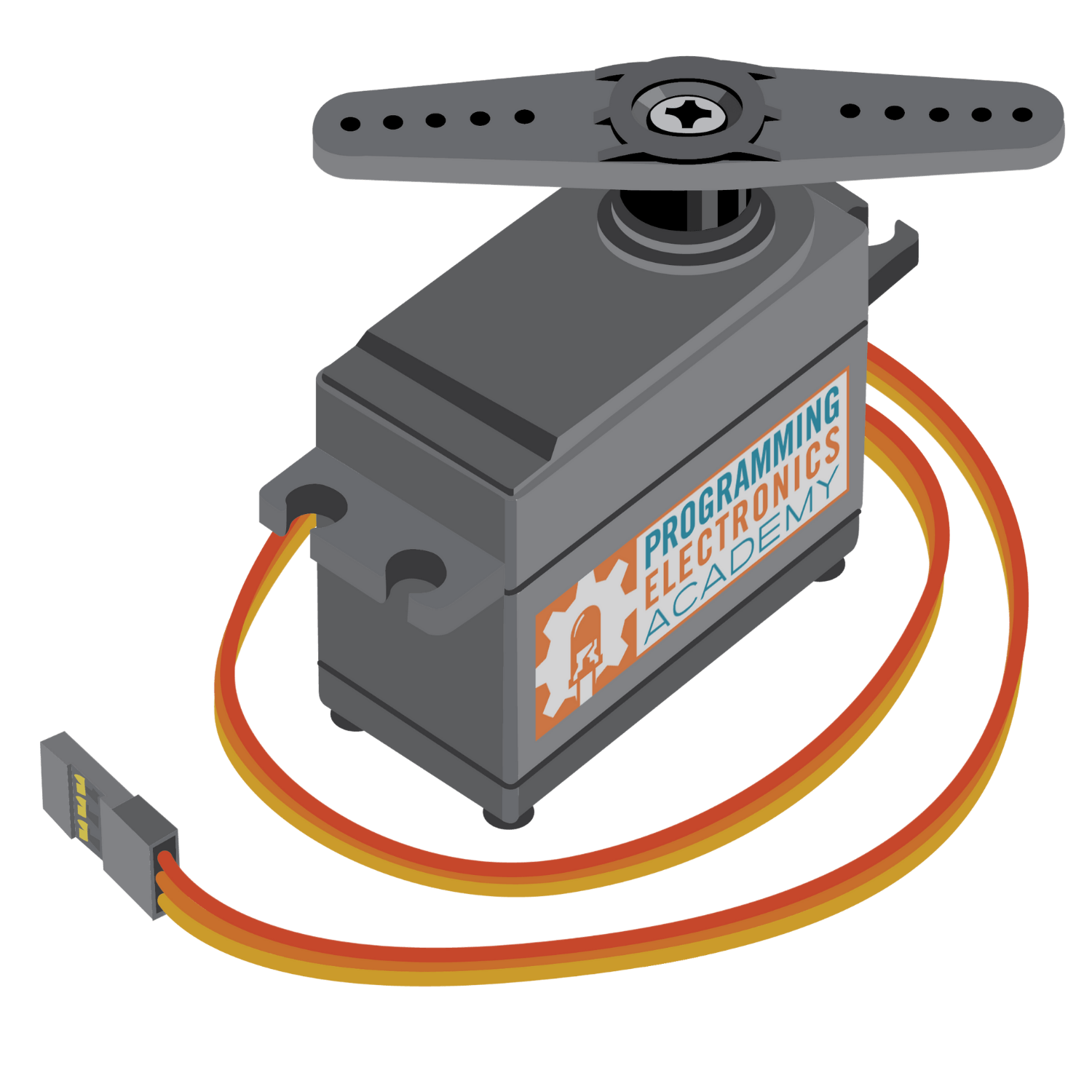
What are Servos?
In short, a servo is a black box (literally) that contains a motor, control electronics, and a sensor that measures rotation speed or angle.
Your microcontroller tells the motor control electronics what to do. It then looks at the position feedback sensor, and then commands the motor to the desired rotation.

Choosing the Right Battery for Your ESP32 Servo
If you do not want to burn out your servos or have constant issues with microcontroller brownouts, then you must put great thought into selecting your battery voltage.
Most servos require between 4.8V to 6V. Exceeding 6V, especially over an extended time, could damage the servo. Some microcontrollers and RC electronics also can’t handle below 5V without brownouts. So, what is the best battery to use for servos?
Lithium batteries operate at either 3.6V or 7.2V, so you can’t use lithium. At least, not without a high power switching buck regulator.
NiHM batteries are 4.8V or 6V, but a 4.8V is a bit weak with servos imho, and 6V NiHM batteries can be over 7V when fully charged. I often use servos with 6V NiMH batteries, but some servo models don’t last more than 5 to 10 hours before failing.
Ni-Cad batteries have the same voltage problem as NiHM (either 4.8V or 6V). They self-discharge faster than NiHM, and have half the energy density (mAh per weight) so you’ll have to recharge them far more often. However, they also put out more instantaneous juice (higher current) than NiMH, so at 4.8V your servos will be less sluggish.
The ESP32 uses 3.6V, so if you don’t mind under-powered servos then go with 4.8V. The lower voltage will extend the lifetime of your servos. I usually use 6V NiMH because I need the extra torque, but my servos only last a few dozen hours – either a gear breaks or the internal electronics go up in smoke.
NiHM batteries don’t supply nearly enough juice as compared to lithium, so you’ll get a voltage drop every time you start up a servo – possibly causing a brownout or reset of your microcontroller.
As such, I usually opt for a two battery system: a 4.8V NiMH for my ESP32, and a separate power bus with a 6V NiMH to power everything else. That way when my servos drain too much power, it won’t cause a microcontroller power reset. You can also try adding some capacitors to your microcontroller power bus to reduce the chance of brownouts.
How Servos Receive Commands
Servos (the cheaper ones) have three wires: ground (black), power (red), and signal (yellow or white).
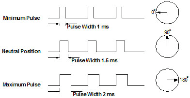
The signal wire receives a square wave pulse, where the width (time spent high) corresponds to the servo angle. The standard is 1ms for far counter clockwise, 1.5ms for centered, and 2ms for far clockwise (see image below). It’s common to have servos deviate from this standard, so only use it as a rule of thumb. I always need to calibrate every servo on all my robots.
When controlling servos, your software is just pulsing a square wave with a specified timing. You call a pin high, use a delay(), then call the pin low. Repeat. Analog servos will require several pulses before it moves to the commanded position, whereas digital servos will typically move to the commanded position after a single pulse.
But… you will likely need your microcontroller to do other things, such as process sensor data, so you can’t just have it pulse and wastefully sit in a delay() function forever. And you may have 10 or 20 servos to simultaneously and independently control.
Therefore, servos should be controlled in the background using PWM or interrupts, which requires a bit of programming. Or, you can download a servo library and be done with it. You can also use a dedicated servo controller board, but that’s for another tutorial.
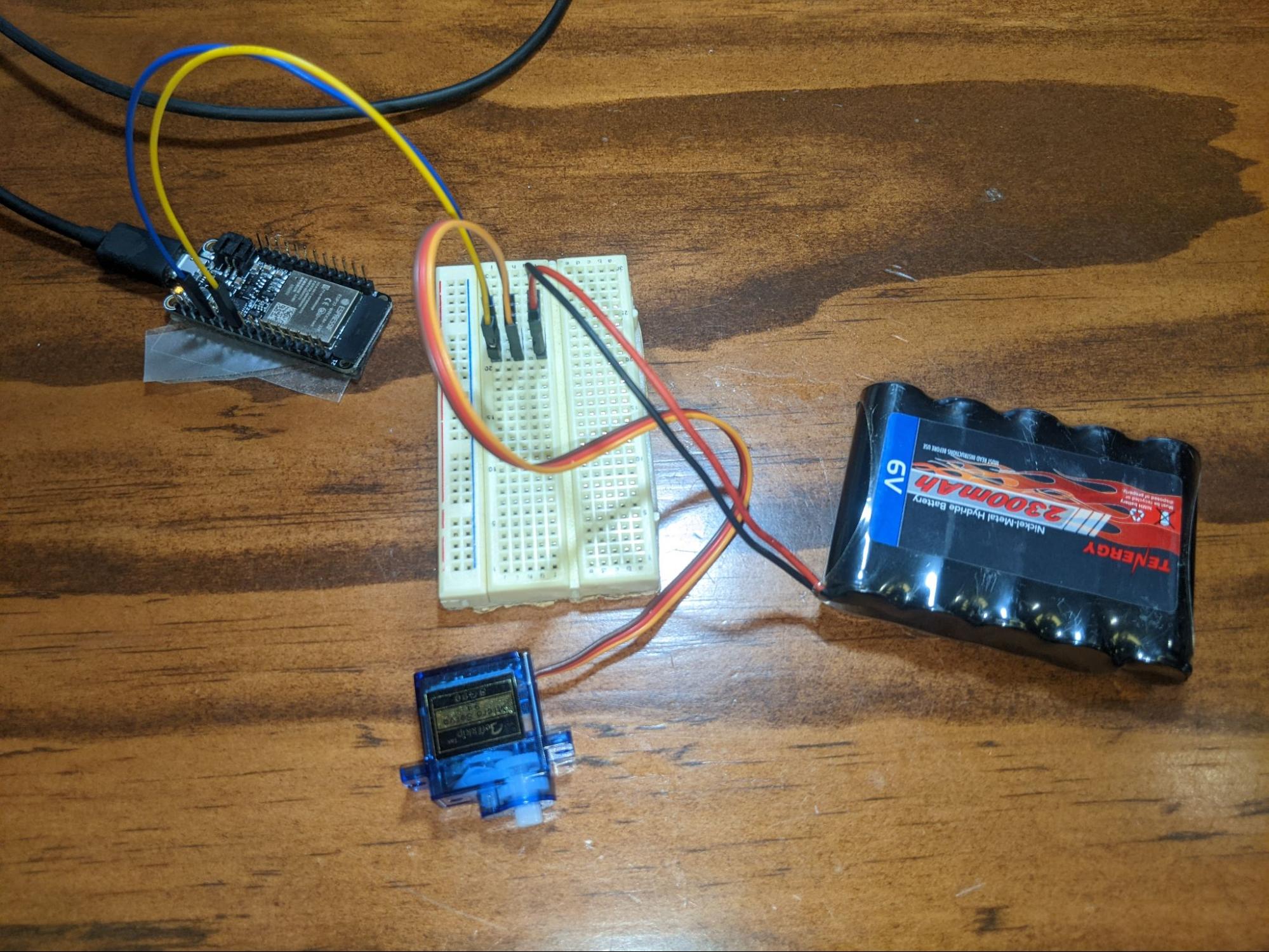
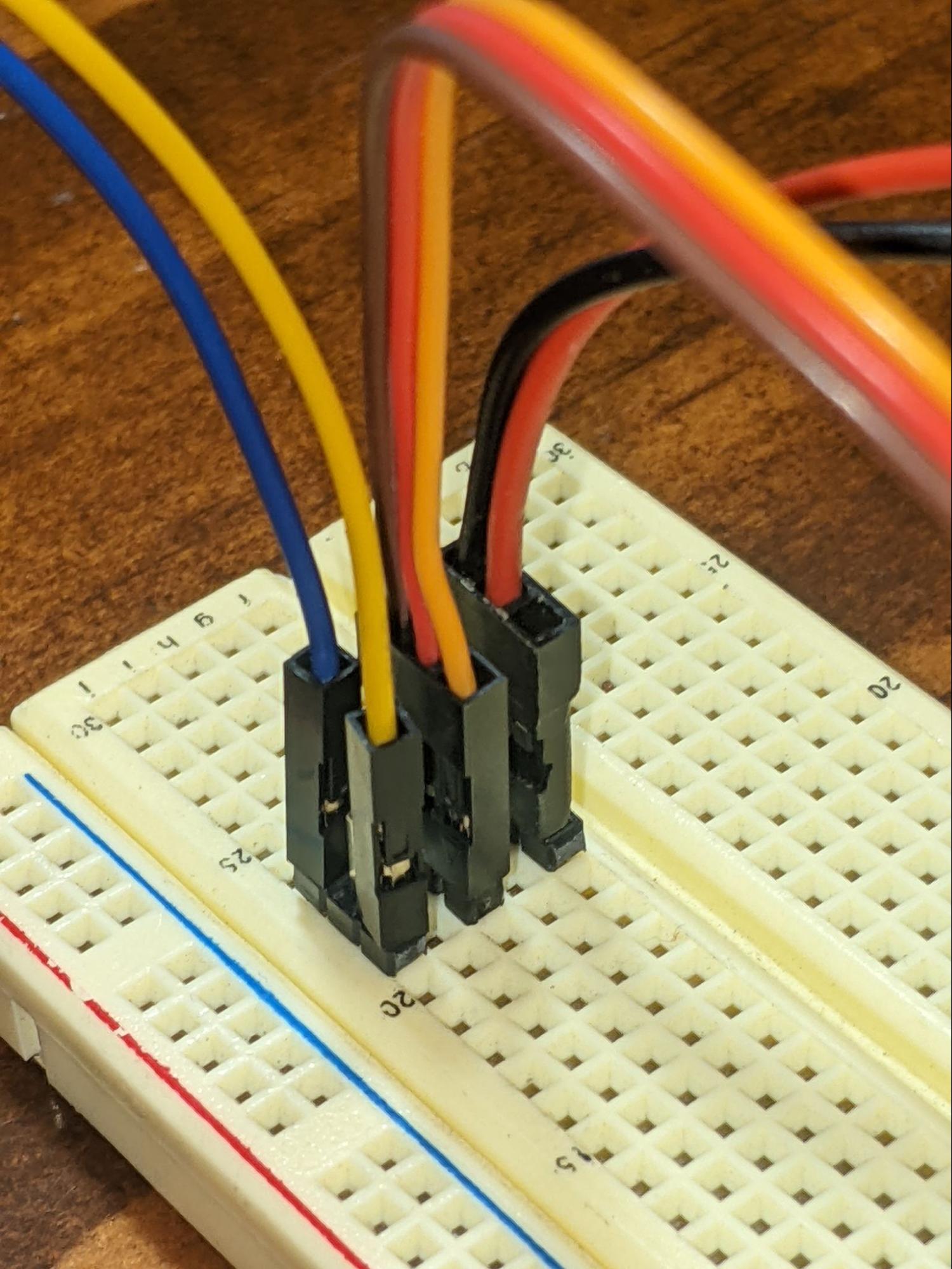
Wiring Up an Example
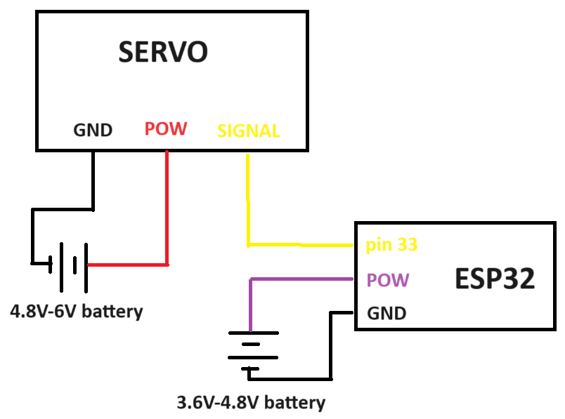
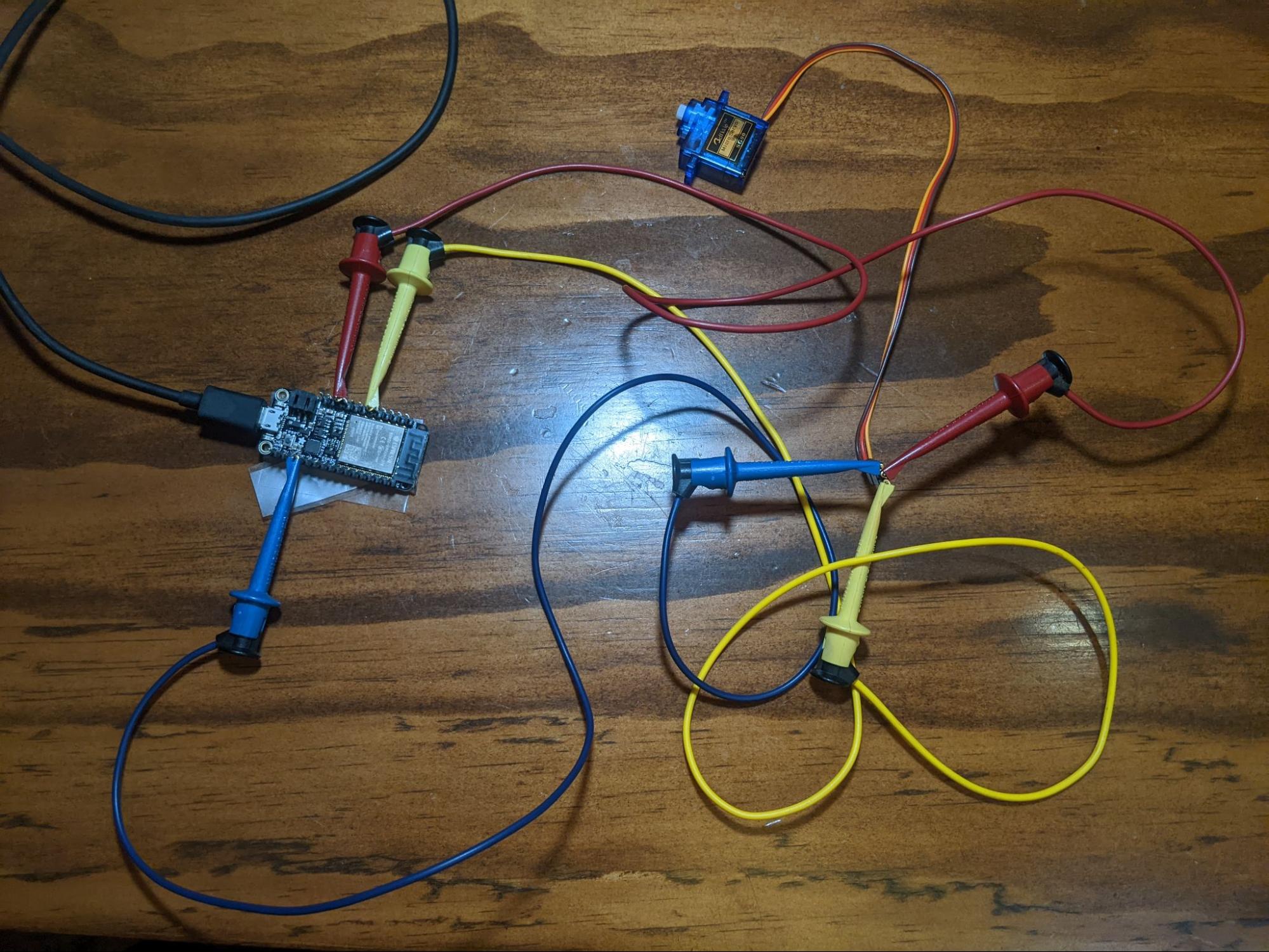
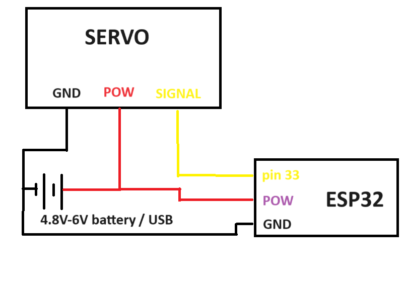
There are many ways you can do this, but I did two. In the first, I used a breadboard and an external battery. In the second method, I used jumper cables and powered the servo directly from USB.
I used the Adafruit HUZZAH32 – ESP32 Feather Board to test the examples, but any other ESP32 board would do. It’s powered via USB, and I’m only using pins GND (ground), USB (for power to servo), and 33 (output to servo).
| Step | ||
|---|---|---|
| Method 1: USB power for ESP32 and separate battery for Servo | ||
| ESP32 GND | to | Battery (-), Servo GND pin |
| ESP32 pin 33 | to | Servo signal pin |
| Battery (+) | to | Servo PWR pin |
| Step | ||
|---|---|---|
| Method 2: USB power for ESP32 and Servo | ||
| ESP32 GND | to | Battery (-), Servo GND pin |
| ESP32 USB | to | Servo PWR pin |
| ESP32 pin 33 | to | Servo signal pin |
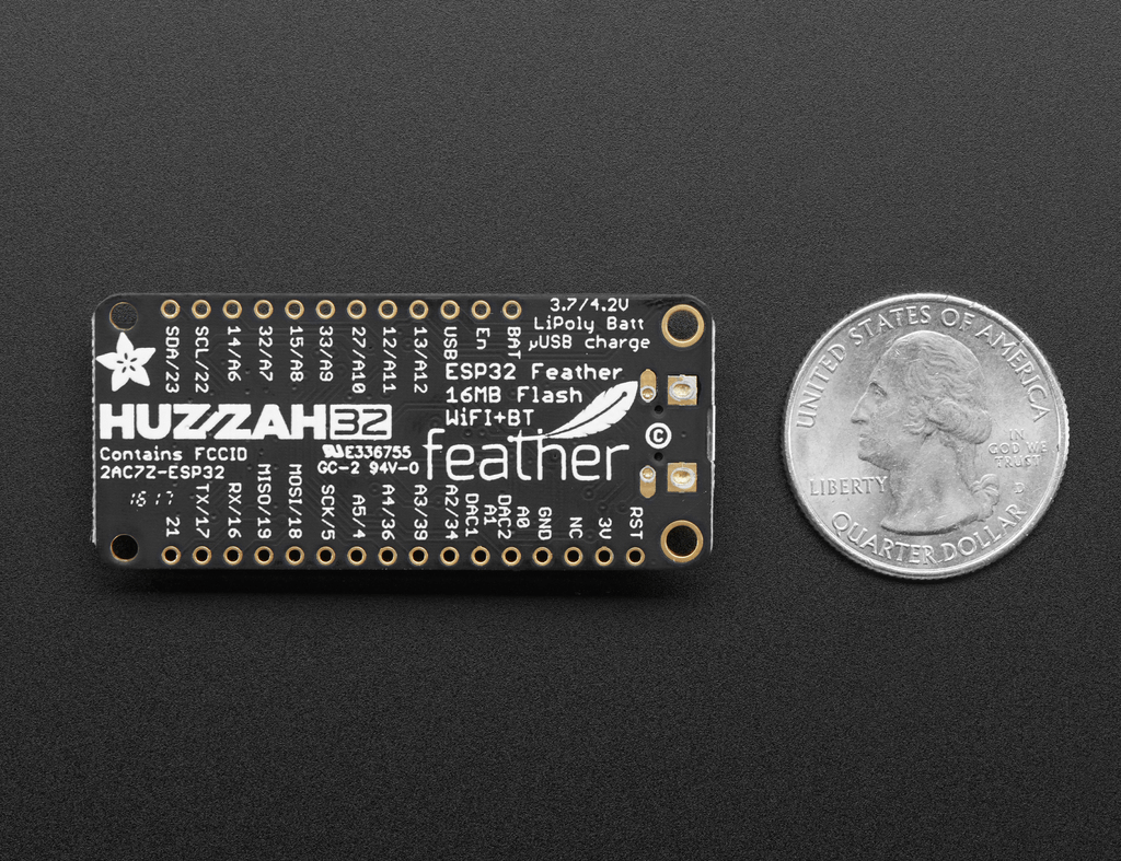
Huzzah32 feather ESP32 pinout:
Installing The ESP32 Servo Library
<rant> I’ve tried nearly every ESP32 servo library for Arduino you can download, and surprisingly most do not work. Nothing but library conflicts and compile errors. Even ESP32 tutorials from otherwise reliable tutorial websites didn’t work for me. I suspect there are versioning conflicts, and maybe libraries aren’t being updated? <end rant>
The only library that worked for me is AnalogWrite, which imho is incredibly clean and simple to implement. Open up your Library tab and do a search for it as shown below, then click install.
If you want more details on how to install an Arduino library, check out this in-depth video lesson we made.
Note: check out the ESP32 ESP23S2 AnalogWrite library (by David Lloyd) on Github for more info.

Once installed, create a new project and copy/paste this below code. Change the servo pin to match your hardware, verify it compiles, then upload to your ESP32. I’ve included extra code – commented out – in case you want to control multiple servos.
#define servo1_pin      33 //pin that connects to servo

//#define servo2_pin      12 //pin that connects to servo
//#define servo3_pin      27 //pin that connects to servo

#include <Servo.h>

Servo servo1 = Servo();  // create servo object to control a servo

//Servo servo2 = Servo();  // left wheel
//Servo servo3 = Servo();  // right wheel

uint8_t pos1 = 180;    //variable to store the servo position

//uint8_t pos2 = 180;    //variable to store the servo position
//uint8_t pos3 = 180;    //variable to store the servo position

void setup() {

  //small delay for proper power up
  delay(150);
  Serial.begin(115200);

  servo1.write(servo1_pin, pos1);
  //servo2.write(servo2_pin, pos2);
  //servo3.write(servo3_pin, pos3);

  Serial.print("nservo position:n");

}

void loop() {

  //control servo
  for(pos1=0;pos1<180;pos1++)

    {

    Serial.println(pos1);
    servo1.write(servo1_pin,pos1);// tell servo to go to position in variable 'pos'
    delay(20);

    }

  //servo2.write(servo2_pin,pos);
  //servo3.write(servo3_pin,pos);

}
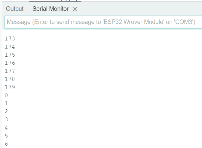
Example Code Output
This example has the servo rotating slowly in one direction, then quickly going back to its starting angle. It’s just an example – your code should be using timing and sensors to control “pos”, i.e. the servo angle. I’ll go into more detail in the next section.
Pre-programmed ESP32 Servo Positioning
Let’s say you have an artistic setup where servos must go through a list of pre-programmed positions. Or maybe you have a robot with arms, and each joint of the arm must move at the same time to a specific location. How do we efficiently do this?
The best way to control multiple servos is to use arrays. You pre-program a list of required positions/angles, and then your code cycles through it over time. The example below controls 3 servos simultaneously, smoothly moving between each of the multiple pre-programmed positions. The commenting should make it self-explanatory. Each array is a new final position, so feel free to add more arrays.
//declare pins that connect to servo

#define servo0_pin      33
#define servo1_pin      12
#define servo2_pin      27

#include <Servo.h>

//create servo objects to control a servo

Servo servo0 = Servo();  // gripper
Servo servo1 = Servo();  // left wheel
Servo servo2 = Servo();  // right wheel

//remember current servo positions

uint8_t pos_s0 = 180;
uint8_t pos_s1 = 180;
uint8_t pos_s2 = 180;

//list of pre-programmed positions (servo 0, servo 1, servo 2)

uint8_t servo_pos_init[3] ={64,119,78};
uint8_t servo_pos_alpha[3]={81,166,114};
uint8_t servo_pos_beta[3] ={27,140,86};

//send a command signal to each servo
void servos_command(void)

  {

  servo0.write(servo0_pin,pos_s0);
  servo1.write(servo1_pin,pos_s1);
  servo2.write(servo2_pin,pos_s2);

  }

//this function gradually moves a servo from one position to the next
//it checks the current position, and if it's not yet the new required position,
//it'll add/subtract to the current position
void servo_goto_pos(uint8_t *pos_list)

  {

  if(pos_s0>pos_list[0])
    pos_s0--;

  else if(pos_s0<pos_list[0])
    pos_s0++;

  if(pos_s1>pos_list[1])
    pos_s1--;

  else if(pos_s1<pos_list[1])
    pos_s1++;

  if(pos_s2>pos_list[2])
    pos_s2--;

  else if(pos_s2<pos_list[2])
    pos_s2++;

  servos_command();

  }

void setup() {

  //small delay for proper power up

  delay(150);

  Serial.begin(115200);

  servo0.write(servo0_pin, pos_s0);
  servo1.write(servo1_pin, pos_s1);
  servo2.write(servo2_pin, pos_s2);
  Serial.print("nstarting up...n");

  //recalling initial positions

  pos_s0=servo_pos_init[0];
  pos_s1=servo_pos_init[1];
  pos_s2=servo_pos_init[2];

  //give capacitors time to charge up properly

  delay(50);

  Serial.print("ninitiating servo positionsn");

  //servos don't know their current position during startup
  //command servos to go to required location before starting robot
  for(uint8_t i=0; i<50; i++)

    {

    servos_command();
    delay(20);

    }

}

void loop() {

  //move servos to pre-programmed positions Alpha

  Serial.print("nMoving to positions Alpha.");
  for(uint8_t i=0; i<180; i++)

    {

    servo_goto_pos(servo_pos_alpha);
    delay(10);//change delay to modify servo speed
    }

  //move servos to pre-programmed positions Beta

  Serial.print("nMoving to positions Beta.");
  for(uint8_t i=0; i<180; i++)

    {

    servo_goto_pos(servo_pos_beta);
    delay(20);//change delay to modify servo speed

    }

}
Servo Code to Extend the Life of your Servos
The two primary ways your servos will fail are: gear failure, and motor-driver burnout. You can reduce the chances of both happening through careful programming of your servos. Let me explain….
Gear Failure
Your servo is rated for some maximum torque, where exceeding that value will cause the gear to break.
There is static torque and dynamic torque.
Static torque is a rotational force applied on a servo, where the servo uses power to keep itself from rotating. For example, imagine a robot using a shoulder servo to hold out its arm straight. Gravity is pulling the arm down, but applied torque is countering that force and holding the arm up motionless.
Dynamic torque is an accelerating or decelerating rotational force, where the servo uses power to change the rotating motion. Imagine a robot swinging its arm around very fast, then using the shoulder servo to suddenly bring the arm to a stop. Decelerating the momentum in the moving arm is a dynamic torque.
While static torque is dependent on physics, dynamic torque can be controlled via software. Your servo code should slowly ease your system into max speed, and gradually slow down into a full stop. Quick robotic jerking motions can break your servos.
Just one additional note… You can buy the MG (metal gear) version of servos (at a premium price). But don’t be fooled, they aren’t necessarily any stronger. Whenever a servo of mine stops working, I immediately open it up to determine why. On the MG servos, which are supposedly all metal gears, it turns out they often use at least one plastic gear inside. It’s usually the smallest and weakest gear, the one directly attached to the motor. It’s always that one plastic gear that fails (ugh!).
Motor-Driver Burnout
Electronics experience wear and tear just like mechanical parts.
Localized high temperature concentrations, and sudden changes in temperature, create physical mechanical stress on silicon and solder joints. Think of how materials can expand and contract with temperature. Your software should try to give your servos occasional “rest.” You can do this with timers and/or temperature sensors, cooling fans, and by limiting maximum torque.
Very high voltage spikes, although extremely short lived, can exceed chip ratings. Capacitors wear out (or even blow up) under voltage spike conditions, too. Voltage spikes are caused by magnetic field collapse with the servo coil.
If a servo is rotating full speed one way, it has a built up magnetic field with a polarity. If you suddenly reverse the servo to full speed the other direction, it must collapse that magnetic field and build a new one with the opposite polarity. Voltage spike ensues.
When controlling servos, your software ideally shouldn’t instantly reverse servo direction.
In theory, circuit boards are designed to handle these extreme conditions. But, I’ve had countless servos release the magic smoke despite operating within normal conditions. Sub-quality engineering, imho.
End Point Burnout
There is one more cause of servo burnout, and that’s caused by jamming at the servo extremes. Internally, servos are mechanically limited to only rotate between 0 and 180 degrees (or some other fixed amount).
You could command the servo to keep turning, but physically it can’t. If the servo is on the “affordable” end, it may command the motor to indefinitely go full speed into the mechanical stop, causing the motor to overheat and eventually burn out.
The solution is to design your control software to only operate the servo within 3 and 177 degrees (for example), leaving a small margin of wiggle room between each end.
Example Code to Extend Servo Life (Bonus!)
The following code does a few things:
- Minimizes acceleration and deceleration.
- Has a timer to shut down servos to prevent overheating.
- Keeps the servo within the boundaries of 3 and 177.
There are many ways to do this, but below is just one example that you could learn from. Every project is different, do what makes sense for yours.
#define servo1_pin      33 //pin that connects to servo
#include <Servo.h>

Servo servo1 = Servo();  // create servo object to control a servo

uint8_t pos = 90;    //variable to store the servo position

//timers to limit overheating

uint32_t time_overheat=6*60*1000;//if constant operating time exceeds 6 minutes, stop servo to cool down
uint32_t time_cooldown=1*60*1000;//cooldown time of 1 min
uint32_t timer_heating=0;//time spent heating up
uint32_t timer_previous=0;

void setup() {  //small delay for proper power up
  delay(150);
  Serial.begin(115200);
  servo1.write(servo1_pin, pos);
  Serial.print("nrunning servo:n");

}

void loop() {

  Serial.printf("ntimer_heating: %ul",timer_heating);
  //control servo

  if(timer_heating < time_overheat)//if not overheating

    {

    Serial.print("nnot overheating, running servos...");
    timer_previous=millis();//start timer
    for(pos=3;pos<177;pos++)//go one direction

      {

      servo1.write(servo1_pin,pos);// tell servo to go to position in variable 'pos'
      delay(20);

      }

    for(pos=177;pos>3;pos--)//go the other direction

      {

      servo1.write(servo1_pin,pos);// tell servo to go to position in variable 'pos'
      delay(20);

      }

    timer_heating=timer_heating+(millis()-timer_previous);//record time spent moving servo(s)

    }

  timer_previous=millis();//start timer
  delay(123);//do something else with motors off
  if(timer_heating > (millis()-timer_previous))//subtract time spent cooling off
    timer_heating=timer_heating-(millis()-timer_previous);

  else
    timer_heating=0;

}


