From Naptime to Action: ESP32 Deep Sleep with External Wake-Up
The ESP32 can operate in an energy-efficient manner while preserving real-time responsiveness thanks to external wake-up(s), which enables the device to emerge from its low-power state in response to particular external events.
In this lesson, we will look at how to implement an external wake-up in ESP32 deep sleep mode.
We’ll go through the hardware configuration, software implementation, and use cases for this functionality.
By the end of this lesson, you will know:
- How to put an ESP32 board in deep sleep mode
- How to use one GPIO (General Purpose Input/Output) pin to wake up the ESP32
- How to use multiple GPIO pins to wake up the ESP32 and identify which pin triggered the wake-up
Hardware Required
- ESP32 Dev Module
- Breadboard
- Jumper wires
- 2x push buttons
- 2x 10kΩ resistors
Understanding ESP32 Deep Sleep External Wake-Up
The process that causes the microcontroller to leave its low-power state in response to particular external stimuli is known as an external wake-up in the context of the ESP32 deep sleep.
An external wake-up entails using physical triggers, such as button pushes, sensor changes, or even external interrupt signals, as opposed to internal wake-up sources like timers or the internal touch sensors.
The ESP32 strikes a compromise between energy conservation and responsiveness by combining deep sleep mode with external wake-up capabilities.
If you want to learn more about ESP32 deep sleep, check out this article we wrote that spells out all the details.
The Benefits of External Wake-Up(s)
The ESP32’s capacity to be externally awakened from deep sleep brings about a number of significant benefits:
| Benefits of Eternal Wake-Up | |
|---|---|
| Energy efficiency | External wake-up events reduce pointless wake-ups and ensure that the microcontroller wakes up only when essential, saving energy. For battery-powered gadgets, this is especially important since it increases their operating lives. |
| Real-time responsiveness | Although deep sleep conserves energy, it might cause a lag in reaction time for time-sensitive jobs. The ESP32 can respond quickly to key events thanks to external wake-up, preserving real-time responsiveness. |
| Dynamic triggering | External wake-up allows for extending the reach of triggers beyond internal timers or sensors. Complex logic may now be implemented by developers, allowing wake-ups depending on complicated situations involving user input. |
| Event-driven actions | Applications that must operate quickly in response to specific events profit from external wake-ups. Intrusion detection, motion sensing, and industrial automation are a few examples. |
Putting Together a Deep Sleep Program
For writing an awesome code for putting the ESP32 into deep sleep mode and waking it up by using external wake-up functions, you can keep the following code flow in mind:
Selecting the wake-up source – Choose the outside event that will trigger the wake up. A button push, a change in sensor data, or an interrupt signal from a peripheral device might all be the cause of this. We will be using a push button for this.
GPIO pin configuration – Set the chosen GPIO(s) pin to function as an external wake-up source. Specify whether the trigger will activate when the button is pressed (low) or when it is released (high).
Activating the External wake-up source – Before putting the device into deep sleep, activate the external wake-up source by connecting the designated GPIO pin(s) to the wake-up event.
Starting deep sleep – Execute the command to put the ESP32 into deep sleep. This will actually switch it into a power-saving mode.
Monitoring the wake-up event – The ESP32 will stay in deep sleep until the outside event that causes the wake-up takes place. As soon as the event is recognized, the microcontroller wakes up from deep sleep and starts the predefined wake-up procedure.
External Wake-Up Functions
For the sake of this lesson, we have developed the bare minimum code for you to test the external wake-up functions of the ESP32.
There are two different functions for triggering the external wake-up, ext0 and ext1.
Introducing ext0: The Wake-Up Whisperer
Think of your ESP32 microcontroller as it expertly conserves energy by having a pleasant, lengthy slumber in deep sleep mode. What if, though, you wanted it to awaken whenever something intriguing occurred, like a button press? The ext0 external wake-up function is useful in this situation.
Consider ext0 as a vigilant guard posted at a specific entrance on your ESP32 called a GPIO pin. This GPIO pin is comparable to a unique doorbell. The guard (ext0) wakes up the dozing ESP32 and calls out, “Hey, wake up!” whenever someone (or whatever) presses the doorbell by altering the voltage on the GPIO pin.
Mind you, you can only use RTC GPIO pins for this with this wake-up source. These include GPIOs 36, 39, 34, 35, 32, 33, 25, 26, 27, 14, 12, 13, 0, 15, 2, and 4. You can consult the following image to see which pins are RTC GPIO pins. Hint: They’re labeled as RTC GPIO in orange. 😅

As RTC GPIOs are used as the wake-up source in the ext0 option, the RTC peripherals will remain on during deep sleep if this wake-up source is activated.
Basic Code for Testing ext0 Function
const int wakeupPin = 4;  // GPIO 4 for external wake-up
RTC_DATA_ATTR int bootCount = 0;  // Number of reboots

void setup()
{
  Serial.begin(115200);  // Start serial port at 115200 baud rate
  pinMode(wakeupPin, INPUT_PULLUP);  // Declaring the pin with the push button as INPUT_PULLUP
  bootCount++;  // Increment the number of boots by 1
  Serial.println("Boot number: " + String(bootCount));  // Print the boot number

  esp_sleep_enable_ext0_wakeup((gpio_num_t)wakeupPin, LOW);  // Configure external wake-up
  delay(1000);  // Adding a 1 second delay to avoid multiple presses

  Serial.println("I'm going to sleep now.");  // Print a statement before entering deep sleep
  esp_deep_sleep_start();  // Enter deep sleep mode
}

void loop()
{

}
Declare Required Variables (before setup)
The first variable we declare is wakeupPin which is the GPIO pin number we want to use as the external wake-up trigger. The second variable we declare is bootCount, which is a counter for how many times the ESP32 has booted.
const int wakeupPin = 4;  // GPIO 4 for external wake-up
RTC_DATA_ATTR int bootCount = 0;  // Number of reboots
Note that while declaring the bootCount variable, we added the prefix RTC_DATA_ATTR. This saves the value of bootCount in the RTC memory, which is not wiped during deep sleep mode.
Setup()
Whatever we want our ESP32 to do while it is awake is in this next code snippet.
For this example, we just start serial communication, define the mode of the GPIO pin being used for waking up, increment the boot count, and print some messages on the serial monitor window for us to see.
void setup()
{
  Serial.begin(115200);  // Start serial port at 115200 baud rate
  pinMode(wakeupPin, INPUT_PULLUP);  // Declaring the pin with the push button as INPUT_PULLUP
  bootCount++;  // Increment the number of boots by 1

  Serial.println("Boot number: " + String(bootCount));  // Print the boot number
You might be wondering what INPUT_PULLUP means while defining the pin mode.
When a button is not pressed, it is in a floating state, and our ESP32 might be getting garbage data from it.
To avoid this, we define the pin as INPUT_PULLUP. This internally connects the pin to +3.3V within the ESP32, so instead of a floating state, the button is in a +3.3V state. And when the button is pressed, it will change to the GND state.
Selecting the External Wake-Up Source
In this lesson, we select an external wake-up source (as opposed to a wakeup timer like we demonstrate here), more specifically the ext0 function.
esp_sleep_enable_ext0_wakeup((gpio_num_t)wakeupPin, LOW);  // Configure external wake-up
delay(1000);  // Adding a 1 second delay to avoid multiple presses
This function requires two arguments. The first one is the GPIO pin you want to use for waking up the controller. If you’re wondering what gpio_num_t does here, you’re not alone.
gpio_num_t is an enumeration type used to represent the GPIO (General Purpose Input/Output) numbers on the ESP32. This type helps ensure that only valid GPIO numbers are passed to functions that operate on GPIOs.
In this case we are “casting” (sort of like converting) our designated integer pin number as this gpio_num_t type.
If none of that makes any sense – don’t worry! It’s not essential to understand deep sleep.
The second argument is the state of the GPIO that will trigger the wake-up. This can be either HIGH (when the button is released) or LOW (when the button is pressed).
You might also be wondering why there is a delay function called.
Here’s the deal – the ESP32 detects a button press and reboots, all within a few hundred microseconds. And if we consider a human pressing and releasing a button, the minimum time it would take would be about a few hundred milliseconds.
During this short time, the ESP32 would mistake a single press for multiple presses and reboot multiple times – which is not what we want. So we add a delay (one second in our case) to stall the ESP32 while we release the button. It’s also a cheap insurance against the button bouncing.
However, the Flash might not need this delay. ⚡ 😀
Starting Ultra-Low Power Mode
esp_deep_sleep_start(); // Enter deep sleep mode
This gets the microcontroller switched to Deep Sleep power-saving mode and completes our work.
Hardware Setup – Let’s Get To Business!
To set up the hardware, connect one terminal of the push button to GND and the other terminal to GPIO 4 on the ESP32, as shown in the following image.

Step-by-Step Instructions for using ext0
- Launch the Arduino IDE
- Connect the ESP32 board to your computer with a USB cable.
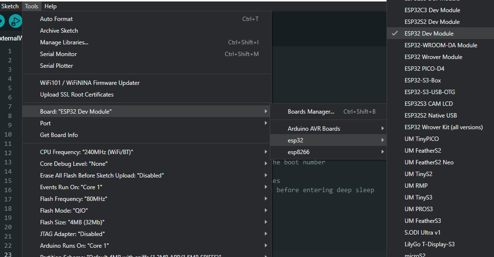
- From the Tools menu, select the board according to which board you are using. For me, it was the ESP32 Dev Module.

- Select the Serial Port to which the ESP32 is connected.
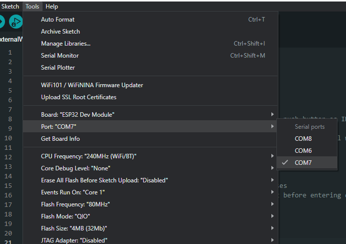
If you see multiple ports (usually shown as COM if you’re on a PC, or dev.cu on a Mac) and you’re unsure which one corresponds to your ESP32 board, that’s fine. Simply disconnect the ESP32 board from the computer and open the Tools menu again. Whichever option was available before but is not available now in the menu is the serial port your ESP32 board was connected to. Connect it again and choose that serial port.
- Use the code provided above. You can copy and paste it in the Arduino IDE if you like, but we encourage typing it out yourself! This will familiarize you with the functions and get you into the habit of writing structured code.
- After selecting the appropriate board and port, upload the code either by clicking the upload button in the top left corner of the window (or by pressing Ctrl+U on a PC or Cmd+U on a Mac).
- When the code is uploaded, open the Serial Monitor window either by clicking on the Serial Monitor button in the top right corner of the window or by pressing Ctrl+Shift+M on a PC or Cmd+Shift+M on a Mac. The Serial Monitor will show something similar to this:
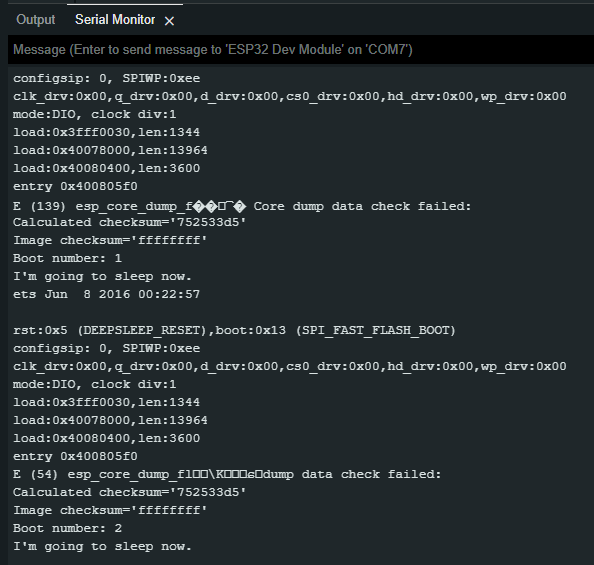
You should see the boot number, which is the number of times the ESP32 has started. The first boot is the default boot, which occurs when the ESP32 is powered. Every boot after that is a result of you poking the ESP32 awake!
Introducing ext1: The Wake-Up Wizard
The ext1 function does the same job as ext0 but differently.
First of all, instead of using the RTC GPIO pins, ext1 uses the RTC controller.
Therefore, in this mode, RTC peripherals and RTC memory can be turned of (this has implications for input pull-ups as discussed below!) Secondly, it also offers the option to use a single pin or multiple pins for triggering the wake-up. And lastly, it can be operated using two different logics:
- Trigger the wake-up if ANY of the selected pins are HIGH.
- Trigger the wake-up if ALL of the selected pins are LOW.
This helps the ESP32’s deep sleep mode adapt to a variety of real-world applications.
Basic Code for Testing ext1 Function
#define BUTTON_PIN_BITMASK 0x14  // 2^2 + 2^4 in hex
RTC_DATA_ATTR int bootCount = 0;  // Number of reboots

void print_GPIO_wake_up()  // Function for determining the GPIO that caused the wake-up
{
  uint64_t GPIO_number = esp_sleep_get_ext1_wakeup_status();
  Serial.print("Wake up caused because of GPIO: ");
  Serial.println((log(GPIO_number))/log(2), 0);
}

void setup()
{
  Serial.begin(115200);  // Start serial port at 115200 baud rate

  bootCount++;  // Increment the number of boots by 1
  Serial.println("Boot number: " + String(bootCount));  // Print the boot number

  print_GPIO_wake_up();  // Determine which GPIO caused the wake-up
  Serial.println("I'm going to sleep now.");  // Print a statement before entering deep sleep

  esp_sleep_enable_ext1_wakeup(BUTTON_PIN_BITMASK, ESP_EXT1_WAKEUP_ANY_HIGH);  // Configure external wake-up
  delay(1000);  // Adding a 1 second delay to avoid multiple presses

  esp_deep_sleep_start();  // Enter deep sleep mod
}

void loop(
{

}
Declare Required Variables (before setup)
We first define BUTTON_PIN_BITMASK, which stores the GPIO numbers of the pins we select to trigger the wake-up. (More on what this bitmask is and how to calculate it is explained after the code).
The second variable we declare is bootCount, which is a counter for how many times the ESP32 has booted.
#define BUTTON_PIN_BITMASK 0x14  // 2^2 + 2^4 in hex
RTC_DATA_ATTR int bootCount = 0;  // Number of rebots
Function for Determining Which GPIO Triggered the Wake-Up
In this function, first we get the value of the wakeup status using esp_sleep_get_ext1_wakeup_staus() which is a built-in function in the ESP32 SDK. Then we determine the GPIO pin that caused the wakeup by using the log() function and print it.
void print_GPIO_wake_up()  // Function for determining the GPIO that caused the wake-up
{
  uint64_t GPIO_number = esp_sleep_get_ext1_wakeup_status();
  Serial.print("Wake up caused because of GPIO: ");
  Serial.println((log(GPIO_number))/log(2), 0);
}
Setup()
Whatever we want our ESP32 to do while it is awake is in the next code snippet. For this example, we just start the serial communication, increment the boot count, print some messages on the serial monitor window for us to see, and call the print_GPIO_wake_up() function to determine the triggering GPIO pin.
void setup()
{
  Serial.begin(115200);  // Start serial port at 115200 baud rate

  bootCount++;  // Increment the number of boots by 1
  Serial.println("Boot number: " + String(bootCount));  // Print the boot number

  print_GPIO_wake_up();  // Determine which GPIO caused the wake-up
  Serial.println("I'm going to sleep now.");  // Print a statement before entering deep sleep
Selecting the External Wake-Up Source
In this lesson, we select the external wake-up source, more specifically the esp_sleep_enable_ext1_wakeup() function.
esp_sleep_enable_ext1_wakeup(BUTTON_PIN_BITMASK, ESP_EXT1_WAKEUP_ANY_HIGH);  // Configure external wake-up

delay(1000);  // Adding a 1 second delay to avoid multiple presses
This function requires two arguments. The first one is the bitmask we defined at the start of the program.
The second argument is the logic we want to follow, either trigger wakeup when any of the selected GPIO pins is HIGH or when all of the selected GPIO pins are LOW. The following keywords are what you use for the second parameter:
ESP_EXT1_WAKEUP_ANY_HIGH: The ESP32 will wake up from deep sleep if any one (or more) of the GPIOs specified in the bitmask (first parameter) are at a HIGH level.
ESP_EXT1_WAKEUP_ALL_LOW: The ESP32 will wake up from deep sleep only if all the GPIOs specified in the bitmask (first parameter) are at a LOW level.The delay function is for the same purpose as it was in the ext0 method. Just a reminder, you can’t beat The Flash! ⚡
Starting Ultra-Low Power Mode
esp_deep_sleep_start(); // Enter deep sleep mode
This gets the microcontroller switched to deep sleep power-saving mode and completes our work.
Calculating the GPIOs Bitmask
To calculate the bitmask, first choose a single or multiple GPIO pins you want to use as the wakeup trigger(s). In the above code, we chose GPIO 2 and GPIO 4.
After that, calculate 2 to the power of the GPIO number. Do this for every pin you choose, and add the results together. 2^2 + 2^4 = 20.
It’s conventional to use a hexadecimal number for the bitmask. To do this, just convert the obtained sum from decimal to hexadecimal. You can use this link for this conversion. The hexadecimal value you get after conversion is the value of the bitmask (in this case 0x14).
You could just use the decimal number 20 – that would work fine, but when you see a number like 20, it looks like a single number, as opposed to a bit max, hence the use of hexadecimal numbers.
In this way you are able to represent multiple pins with a single number – pretty cool!
When using ext1 INPUT_PULLUP doesn’t work…unless
As noted above, when using the ext1 as the wakeup mode, more stuff can be put to sleep (namely the RTC peripherals). But this also has a draw back – the internal pullup and pulldown resistors for the RTC_GPIO pins are disabled, which means using pinMode(somePin, INPUT_PULLUP), will not work!
There is way around this though, and that is by configuring the power down mode to keep the RTC peripherals powered while sleeping. You lose some power savings, but get your internal pullup / pulldown resistors back.
To keep the RTC peripherals on, you would use this line of code before putting the ESP32 into deep sleep mode:
esp_sleep_pd_config(ESP_PD_DOMAIN_RTC_PERIPH, ESP_PD_OPTION_ON);
Hardware Setup – Let’s Get Woke Up!
Set up the hardware as shown in the following image. We will use GPIO 2 and GPIO 4 as the wake-up triggers.

You might notice we have also used resistors for this method. We went for the logic in which the wakeup is triggered when any of the selected pins is HIGH. Since the trigger is in the HIGH state, we need to keep the buttons in the LOW state. For that, we need to PULL DOWN the push buttons.
What if we selected the other logic in which the wakeup was triggered when all of the selected pins were LOW? How would that change the above circuit?
Step-by-Step Instructions for ext1
Following the same instructions as given for the ext0 method, use the new code for ext1. You should see something similar to this in the serial monitor window:
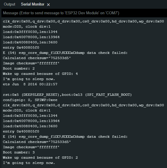
You should see the boot number and the GPIO pin that caused the wakeup. The first boot is the default boot, which occurs when the ESP32 is powered. Every boot after that is the result of a push button.
Try on Your Own Challenges
- Edit the ext0 method code to set the wakeup to be triggered in the HIGH state. What changes would that cause when a button is pressed and released?
- Edit the ext1 method code to select GPIO 12 and GPIO 13 as the triggering pins. Will you have to calculate the bitmask again?
- Use the “trigger wakeup when all selected pins are low” logic in the ext1 method. How would that change the hardware setup?


