pong Arduino game you can fit in your pocket!
Check out this retro pong Arduino game built with an Arduino UNO microcontroller development board! We have included the Arduino code and circuit digram at the bottom of this post so you can easily build this yourself too.
Steve Stefanidis, who does technical writing for PEA, designed this really fun retro pong game with 5 components (OK and a resistor too!), and I think you’ll get a kick out of how it works!
The Build
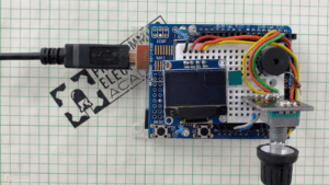
Steve used an Arduino nano for his design, when I built it , I ended up using an Arduino UNO with a proto-shield on top – if you have no idea what an Arduino is, or what an Arduino shield is, make sure to check out our our other YouTube videos that go into all those kind of details.
Those shields can come in handy, because it has a built in solderless breadboard for prototyping something small right on top.
The display for this is an OLED module. You can pick these up anywhere, I got mine on amazon. These things are super cheap and pretty easy to use with the graphics libraries out there – Steve used the u8glib library for this project.
A piezo buzzer is for adding sound effects for when the ball hits the paddle, wall, and when you lose. I was impressed with the buzzer noises, coming from a simple piezo buzzer – they sound pretty good! It really reminds me of an old school game.
The last part is a rotary encoder. This is the dial that allows you to move the paddle back and forth – you can also press down on the dial, and this acts as a button that is used for adjusting different settings which I show you in a moment.
Rotary encoders are great for building interfaces with limited space, where you need to make selections. With the right code you can track exactly where the shaft is any given time. If you are ever interested in learning how to program these, we have an entire course at PEA that covers how to write code to use these – you learn a bunch about interrupts in the process – it’s pretty cool!
This rotary encoder comes attached to a PCB base making it breadboard friendly. Again, this is all stuff you can easily get on amazon or any electronics vendor for that matter.
That’s pretty much it for components of this pong Arduino game, save a single 100Ohm resistor for the piezo buzzer.
Arduino Pong Game Play
I already uploaded the code onto the Arduino board, so once this is powered up you start playing immediately.
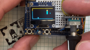
You’ll notice when I first built this, to my surprise I had used an OLED display that had a yellow only bar at the top. So the whole top quarter of the screen is yellow, and the bottom half is blue. I ended up really liking the 2 tone look – it sort of reminded me of a glitch I might see on some old arcade game back of a pizza shop. I am no gamer, but I used to play pong in a local pizza shop when I was kid…good memories.
To move the paddle you just rotate the rotary encoder back and forth – it’s super responsive – and if you see me missing the ball, it’s just because my gaming skills are subpar…
On start up, the default settings are pretty easy. The ball moves nice and slow, when it hits a wall, the return angle is easy to predict – it’s just straight up easy mode.
On the right hand side is a counter of all the times you have lost – because I really need to be reminded how much I stink at pong….
Game Settings
To adjust the setting you just press in on the rotary encoder – this puts the game into settings mode, and on the top right you see the first option. You’ll also notice, the ball and paddle go from being filled to empty, with only an outline.
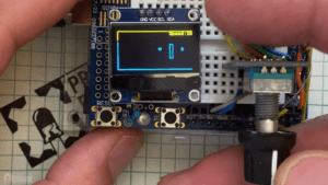
The settings are easy to navigate, and again, the rotary encoder handles all the adjustments. You can have sound ON (1)or Off (0), you just rotate to get to the spot you want.
When you’re happy with the selection you press the rotary encoder again, and this brings you to Speed: which can be adjusted from 1 to 19. This thing can start going super quick!
Press again, and you get to Skew. Skew controls how the balls deflects off the walls and paddle. The higher the skew, the more variability in the directions the ball will bounce – and the harder the game becomes.
The final selection is the paddle size. Once you’ve made the last selection, the game starts again.
Game Thoughts
Pong’s such a classic! And this pong Arduino version is no exception. What I find fascinating about games is that sometimes it doesn’t take amazing graphics to keep us entertained, just some basic randomness and simple play mechanics seem to do the job. All which can be programmed using an Arduino.
In total, this was just over 400 lines of code. You really should try this out.
If you ‘d like another video diving into the code be sure to let us know down in the comments and hit the like button.
Components:
These are affiliate links that help us buy golden toilets for our mega yacht.
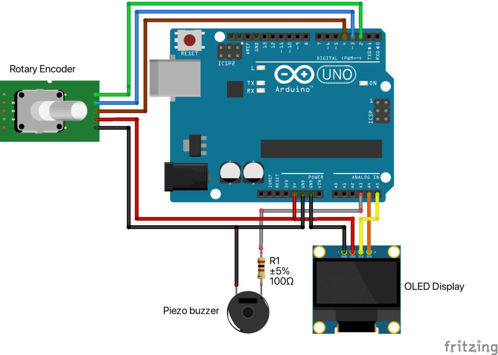
Circuit Diagram:
Pong Arduino Code:
Click here to download the Arduino sketch if you are getting errors from cutting and pasting.
#include <U8glib.h>

// Use the emum type to create unique values for our constants
enum {
    POSITION = 0,
    SOUND,
    SPEED,
    SKEW,
    SIZE,
    LAST
};

// Define and initialize our data structure for the parameters.
// The paddle position is changed simply by rotating the RE shaft when in normal game mode.
// There are 4 adjustable (i.e. customizable) parameters: sound, ball speed, skew and paddle size.
// To enter the adjustment/customization mode: press the RE switch. The parameters will cycle sequentially
// from sound->speed->skew->size and then the normal game play will be resumed with the adjusted values.
struct {
    const char *name;
    byte        minValue;
    byte        maxValue;
    byte        incValue;
    byte        activeValue;
} params[] = {
    {"Position", 0,  0,  2,  0},   // paddle position
    {"Sound",    0,  1,  1,  1},   // game sound
    {"Speed",    1, 19,  1,  4},   // ball speed
    {"Skew",     1, 15,  1,  1},   // ball skew
    {"Size",    10, 45,  5, 25}    // paddle size
};

const byte numParams = sizeof(params) / sizeof(params[0]);
const byte speakerPin = A3;

byte reMin, reMax, countIncr; // RE minimum, maximum and increment size for currently selected parameter
int screenWidth;              // LCD display's width in pixels
int screenHeight;             // LCD display's height in pixels
int bx, by, br;               // ball's center coordinate (x,y) and its radius respectively
byte px, py;                  // x and y coordinates of paddle's the top left corner
byte allowSound;              // enables or disables sound
int xinc;                     // ball increment in x-direction
int yinc;                     // ball increment in y-direction
byte skew;                    // current skew value
byte pHeight;                 // paddle size (i.e. height in pixels)
const byte pWidth = 6;        // paddle width (in pixels)
unsigned int gameScore = 0;   // tracks the score
boolean inAdjustMode = false; // normal game mode by default

char strBuf[16];              // used for string formatting

const unsigned int ROTARY_ENC_PIN_A  = 2;
const unsigned int ROTARY_ENC_PIN_B  = 3;
const unsigned int ROTARY_ENC_SWITCH = 4;

#define NO_CHANGE 0
#define TURN_CW   1
#define TURN_CCW  2

// Direction     +- ccw  -+  N  +-  cw  -+
// Index         0  1  2  3  4  5  6  7  8
byte aState[] = {3, 2, 0, 1, 3, 2, 0, 1, 3};
byte lastState = 0;
volatile int count[numParams] = {0};
unsigned int Index = 4;
volatile byte encoderStatus = NO_CHANGE;
int switchPressCount;

// Enable the display type to be used. Currently, only 3 displays listed below have been tested.
U8GLIB_SSD1306_128X64 u8g(U8G_I2C_OPT_NONE|U8G_I2C_OPT_FAST); // for 1306 I2C (128x64)
//U8GLIB_SSD1306_ADAFRUIT_128X64 u8g(6, 7, 9, 8, 10);  // D0=6, D1=7, RES=10, DC=8, CS=9
//U8GLIB_PCD8544 u8g(6, 7, 9, 8, 10);  // CLK=6, DIN=7, DC=8, CE=9, RST=10 // for 5110 SPI (84x48)


void setup()
{
  Serial.begin(9600);
  Serial.print("Starting Game...");

  // Acquire the display size and dump it out.
  screenWidth  = u8g.getWidth();
  screenHeight = u8g.getHeight();
  Serial.print(screenWidth);
  Serial.print("x");
  Serial.println(screenHeight);

  // Clear the screen
  u8g.firstPage();
  do {}
     while(u8g.nextPage());

  // These variables will hold the currently-set parameter values.
  allowSound = params[SOUND].activeValue; // sets sound on/off
  xinc = params[SPEED].activeValue;       // defines the speed
  skew = params[SKEW].activeValue;        // defines the skew
  pHeight = params[SIZE].activeValue;     // defines paddle size

  // Setup paddle parameters (refers to the top left corner of the paddle)
  params[POSITION].minValue = 0;
  params[POSITION].maxValue = screenHeight - pHeight;
  params[POSITION].activeValue = (params[POSITION].maxValue - params[POSITION].minValue) / 2; // Center the paddle position
  setREParams(POSITION);

  // Initialize the RE's settings, based on the default parameter values.
  for (int i = 0; i < numParams; i++)
      count[i] = params[i].activeValue;

/*      _ _
      /     \
     |   *   |  [bx,by] is the coordinate of the ball's center
      \ _ _ /

         |<->|   br is the ball's radius
*/

  // Configure starting parameters
  randomSeed(analogRead(1));
  br = 2;
  bx = br;
  by = random(br, screenHeight - br);
  yinc = random(-skew, skew);
  px = 0.7 * screenWidth;
  py = params[POSITION].maxValue - params[POSITION].activeValue;

  pinMode(speakerPin, OUTPUT);

  // Set up the gfx font
  u8g.setFont(u8g_font_profont10r);

  // Track the number of times the RE switch has been pressed.
  switchPressCount = 0;

  pinMode(ROTARY_ENC_PIN_A,  INPUT);
  pinMode(ROTARY_ENC_PIN_B,  INPUT);
  pinMode(ROTARY_ENC_SWITCH, INPUT_PULLUP);

  attachInterrupt(digitalPinToInterrupt(ROTARY_ENC_PIN_A), readEncoderStatus, CHANGE);
  attachInterrupt(digitalPinToInterrupt(ROTARY_ENC_PIN_B), readEncoderStatus, CHANGE);
}

void readEncoderStatus()
{
  byte currState;

  // We form our current state value by assigning the signal
  // from pin A to bit1 and signal from pin B to bit0
  currState = (digitalRead(ROTARY_ENC_PIN_A) * 2) + digitalRead(ROTARY_ENC_PIN_B);
  if (currState != lastState)
  {
    // New state detected.
    // Check if we're moving in the clockwise direction
    if (currState == aState[Index+1])
    {
      Index++;
      if (8 == Index)
      {
        // Successfully completed the sequence of 3->2->0->1->3 for cw.
        // Increment the count and reset the index to the nominal setting.
        count[switchPressCount] += countIncr;
        if (count[switchPressCount] > reMax)
          count[switchPressCount] = reMax;
        Index = 4;
        encoderStatus = TURN_CW;
      }
    }
    // Check if we're moving in the counterclockwise direction
    else if (currState == aState[Index-1])
    {
      Index--;
      if (0 == Index)
      {
        // Successfully completed the sequence of 3->1->0->2->3 for ccw.
        // Decrement the count and reset the index to the nominal setting.
        count[switchPressCount] -= countIncr;
        if (count[switchPressCount] < reMin)
          count[switchPressCount] = reMin;
        Index = 4;
        encoderStatus = TURN_CCW;
      }
    }
    lastState = currState;
  }
}

void setREParams(int paramIndex)
{
  countIncr = params[paramIndex].incValue;
  reMin = params[paramIndex].minValue;
  reMax = params[paramIndex].maxValue;
}

void CheckEncoder()
{
  // If encoder shaft was turned, print out the current status
  if (encoderStatus != NO_CHANGE)
  {
    int countTemp;

    noInterrupts();     // Disable interrupts
    countTemp = count[switchPressCount];  // Save the variable
    interrupts();       // Re-enable interrupts
    Serial.print(encoderStatus == TURN_CW ? "CW   [" : "CCW  [");
    Serial.print(switchPressCount);
    Serial.print("] ");
    Serial.println(countTemp);  // Use the saved variable
    encoderStatus = NO_CHANGE;
  }

  if (!digitalRead(ROTARY_ENC_SWITCH))
  {
    // Switch was pushed (active LOW).
    // Reset the count and debounce the switch contacts.
    switchPressCount++;
    delay(100);
    while (!digitalRead(ROTARY_ENC_SWITCH));
    delay(100);
  }
}

void playSound(int frequency, int duration)
{
  if (allowSound)
  {
    tone(speakerPin, frequency, duration);
  }
}

void wallSound()
{
  playSound(4000, 50);
}

void paddleSound()
{
  playSound(2000, 50);
}

void scoreSound()
{
  int del = 300, hiFreq = 1250, loFreq = 200;

  for (int i = 0; i < 2; i++)
  {
    playSound(hiFreq, 450);
    delay(del);
    playSound(loFreq, 450);
    delay(del);
  }
}

// This function checks the RE switch counter and displays the adjustment values
// for sound, speed, skew and size - depending on the counter's value.
void CheckAdjustMode(void)
{
  switch (switchPressCount)
  {
    case SOUND:
    case SPEED:
    case SKEW:
    case SIZE:
      // Set the proper adjustment range for this parameter
      setREParams(switchPressCount);

      // Save the selected RE value for this parameter
      params[switchPressCount].activeValue = count[switchPressCount];

      // Form the string and display in the top right corner of the display
      sprintf(strBuf, "%s:%d", params[switchPressCount].name, params[switchPressCount].activeValue);
      u8g.drawStr(screenWidth-u8g.getStrPixelWidth(strBuf), u8g.getFontAscent(), strBuf);

      // Update the selected values for the next screen draw
      allowSound = params[SOUND].activeValue;
      xinc = (xinc < 0) ? -params[SPEED].activeValue: params[SPEED].activeValue;
      skew = params[SKEW].activeValue;
      pHeight = params[SIZE].activeValue;
      inAdjustMode = true;
      break;

    case LAST:
      // Exiting customization; restore to normal game play
      switchPressCount = 0;
      params[switchPressCount].maxValue = screenHeight - pHeight;
      setREParams(switchPressCount);
      inAdjustMode = false;
      break;

    default:
      inAdjustMode = false;
      break;
  }
}

void loop()
{
  static int frameCount = 0;
  boolean lostPoint = false;

  CheckEncoder();

  // Determine the paddle location
  py = params[POSITION].maxValue - constrain(count[POSITION], params[POSITION].minValue, params[POSITION].maxValue);

  // If the ball reached the left wall, reverse its direction
  if (xinc <= 0 && bx <= br)
  {
    xinc *= -1;
    wallSound();
  }

  // See if the ball hit the paddle...
  if((xinc > 0) && (bx+br >= px) && (by+br >= py) && (by <= py+pHeight+br) && (bx-br <= px+pWidth))
  {
    // Reverse its x-direction
    xinc *= -1;

    // Reverse its y-direction, depending on where the ball touched the paddle.
    // The top 3/7 of the paddle bounces the ball in one direction and the bottom 3/7 of the paddle
    // bounces it in the opposite direction (with some randomness thrown in, as a function of skew).
    if (by <= py + (3 * pHeight) / 7)
      yinc = -random(1, skew + 1); // Add some randomness to the ball motion, based on the current skew setting
    if (by >= py + (4 * pHeight) / 7)
      yinc = random(1, skew + 1);  // Add some randomness to the ball motion, based on the current skew setting

    paddleSound();
  }

  // Check if the ball is clear of the top and bottom walls
  if (by+yinc >= (screenHeight-br) ||   // is the ball above the bottom wall, or
     (by+yinc <= br))                   // is the ball below the top wall
  {
    // ...bounce it off the wall
    yinc *= -1;
    wallSound();
  }

  // See if the ball missed the paddle and reached the right side.
  // If so, update score and relaunch it from the left side.
  if (bx >= screenWidth)
  {
    xinc = params[SPEED].activeValue;
    yinc = random(-skew, skew);
    bx = px - ((px / xinc) *  xinc);
    by = random(br, screenHeight-br);

    if (inAdjustMode == false)
    {
      // We're not in adjustment mode; allow the score to be reflected.
      gameScore++;
      lostPoint = true;
      Serial.println("Lost Point - incremented gameScore.");
    }
  }
  else
  {
    // Advance the ball in the horizontal and vertical directions
    bx += xinc;
    by += yinc;
  }

  u8g.firstPage();
  do {
    if (lostPoint == false)
    {
      // Draw normal screens: regular play or adjust screens
      if (!(frameCount++ % 2))
      {
        // Check the Adjust Mode on alternate frames; this gives better performance
        CheckAdjustMode();
      }

      // Draw the borders
      u8g.drawLine(0, 0, screenWidth-1, 0);
      u8g.drawLine(0, 0, 0, screenHeight-1);
      u8g.drawLine(0, screenHeight-1, screenWidth-1, screenHeight-1);

      // Make things look different when in adjust mode vs play mode
      if (inAdjustMode == true)
      {
        u8g.drawCircle(bx, by, br, U8G_DRAW_ALL); // Draw the ball as a circle
        u8g.drawFrame(px, py, pWidth, pHeight);   // Draw the paddle as a frame
      }
      else
      {
        u8g.drawDisc(bx, by, br, U8G_DRAW_ALL);   // Draw the ball as a disc (i.e. solid circle)
        u8g.drawRBox(px, py, pWidth, pHeight, 2); // Draw paddle as solid box; use rounded corners with a radius of 2
      }

      sprintf(strBuf, "%d", gameScore);
      u8g.drawStr((px+pWidth+screenWidth-u8g.getStrPixelWidth(strBuf))/2, screenHeight/2, strBuf);
    }
    else
    {
      // Display the "You Lose" screen
      u8g.setFont(u8g_font_gdb20r); // switch to bigger font
      strcpy (strBuf, "TRY");
      u8g.drawStr((screenWidth-u8g.getStrPixelWidth(strBuf))/2, screenHeight/2, strBuf);
      strcpy (strBuf, "AGAIN!");
      u8g.drawStr((screenWidth-u8g.getStrPixelWidth(strBuf))/2, screenHeight, strBuf);
      u8g.setFont(u8g_font_profont10r); // switch back to our normal font
     }
  } while (u8g.nextPage());

  if (lostPoint == true)
  {
    // Play annoying sound and let the user see the "You Lose" screen.
    scoreSound();
    delay(200);
  }
}


I appreciate your coding tips and posting this project. The project looks like so much fun and I am excited to get it to work, but I could not get it past the compile sketch step. I got a lot of errors. I don’t know enough about coding to know how to fix them…
Sorry about that issue Kathryn – it seems to be an issue with how the code is embedded on the website. I have added a download link for the actual sketch and folder.
Thank you so much! Everything worked and the game is very well done. It is the best Arduino Pong game I have ever seen.
Awesome! Thanks so much!
How Excellent ! Is there any plan to post an explanation of the the code ? Mr Stefanidis is beyond my reach .
IN THE OLED IF YOU CONNECT SDA TO SDA AND SCL TO SCL? I’TS WORK TOO.
I took this and made it work with an old scrapped LCD from the Wanhao i3 3d printer, I had managed to map the EXP1 pins (10) and I made it all work with your example!. It is a perfect fit!, the LCD has it’s own encoder and buzzer/beep. So to resume, you made my day!. tks!
Very cool – Nice Gerry! Thanks for passing this on!
Hey there Michael,
Im pretty new to the arduino and coding for that matter. I cant seem to get the board to hold memory when the power has been disconnected (store the code on the board) i did read something about EEPROM? Just wondering if you could assist?
Thanks mate.
Hi Cameron, yes, if you would like data to persist after power has been turned off and on, you would need to use the EEPROM. Arduino has a library for using it here:
https://docs.arduino.cc/learn/built-in-libraries/eeprom
We’ll have to do an in depth lesson on this at some point!
Perfect, thanks heaps for your help. Much appreciated.
Looks like ill be signing up for one of your courses!
How do I get the U8glib.h file?
Great question Bob! You’ll need to install the U8glib library in the Arduino IDE. Here is lesson on how to do that:
https://www.programmingelectronics.com/installing-arduino-libraries/