
Serial Communication with Arduino
Are you wondering what the heck serial communication is?
Maybe you have been using some functions from the Arduino Serial library, like Serial.begin() and Serial.print() and they leave you wondering more about this serial communication thing – I mean, how does it actually work!?
In this lesson you will learn:
- What is “serial communication”?
- What is a USART anyway?
- The nitty gritty of basic serial communication
- The different roles of start bits, data frames, parity bits, and stop bits
- What the heck baud rate it – and why it is SO crucial
- The (lack of) significance of the baud rate 9600
Part 1
Part 2
Part 3

Don’t get scared!
OK – before we start, I want to warn you that this lesson is filled with technical terms, probably like 572 of them!
I know when you’re new to electronics, all this crazy sounding jargon can be confusing, and you might think it will all be way over your head.
And it might be all “over your head” for a while (it still might be over my head 😉 – but as you get more familiar with these terms, and see them used and explained in different ways, over time all the crazy stuff will start to sink in.
I’ll try to explain all the jargon along the way as best as I can, but just in case you miss something… here is a chart listing all the terms used here:
| TERM | DESCRIPTION |
|---|---|
| UART | Universal Asynchronous Receiver/Transmitter |
| USART | Universal Synchronous/Asynchronous Receiver/Transmitter |
| SPI | Serial Peripheral Interface |
| I2C | Inter-Integrated Circuit |
| ATMEGA328P Microcontroller | The primary microcontroller used On Arduino UNO and MEGA – has built-in UART |
| ATmega16U2 Microcontroller | A microcontroller used on the Arduino UNO and MEGA that has a built in USART. This microcontroller is used as a USB to serial converter. |
| RX | Receive. Often, the connection designated to receive a signal is marked with RX. |
| TX | Transmit. Often, the connection designated to transmit a signal is marked with TX. |
| USB | Universal Serial Bus |
| TTL | Transistor-transistor logic |
| ASCII | American Standard Code For Information Interchange |
What the heck is serial communication?
In a nutshell, serial communication is a method of sending and receiving information one bit at a time.
Serial communication takes many different forms, we will only discuss one of them in detail here.
Programming Electronics Academy members, check out the Arduino Course for Absolute Beginners to practice using the Serial Library in your code.
Not a member yet? Sign up here.
Just like there are many ways to communicate from one person to another, there are many ways to serially communicate from one device to another.
Probably the most familiar method of serial communication is over USB. If you didn’t know, USB stands for Universal Serial Bus.
USB is a serial communication protocol. A protocol is just a way of doing something. Maybe you have a protocol for what to do if you can’t find your phone…
- Curse a couple times
- Mentally walk through the places it could be
- Look in the last room you were in
- Blame the kids for losing your phone
- Look on the bathroom shelf
- Get one of your family members to call you, so you can hear it ring in the basement, buried in the laundry basket
USB is but one of many serial communication protocols that your Arduino can use. It’s also able to communicate using these common protocols…
- Serial Peripheral Interface (SPI)
- Inter-Integrated Circuit (I2C)
- and “TTL serial” using a USART
This last method which uses a USART is by far the simplest method of serial communication and what we’ll use as the starting point for a fundamental understanding of how serial communication works.
So what is this U(S)ART thing?
Many microcontrollers come equipped with a simple way to communicate serially – using a USART. USART stands for Universal Synchronous/Asynchronous Receiver/Transmitter.
Wow – that’s one heck of a name! But let’s dive in – it actually way more reasonable than at first glance.
A USART is a piece of hardware. You’ll find it as either a stand-alone integrated circuit, or built right into a microcontroller.
An Arduino UNO for example uses an ATMEGA328P microcontroller which has a built-in USART.
This built-in USART (which uses the RX/TX pins on the Arduino) can send bytes of data serially to a different microcontroller on the Arduino UNO board, the ATMEGA16U2, which is used to handle the serial communication over USB.
USARTs allow us to take data in parallel from one device, convert it into a serial transmission, and then transform it back again into parallel data.
Now I want to draw attention to the Synchronous/Asynchronous part of USART for a moment – because that I think is most confusing. When serial communication protocols are synchronous (for example I2C, SPI) they use a clock signal for synchronizing the transmission from the sender to the receiver. The clock signal is what actively keeps the two in unison.
With an asynchronous protocol, there is no clock signal to synchronize the communication – which is why it requires a baud rate the receiver and the transmitter agree upon beforehand. We’ll be talking more about baud rate in just a moment.
The flavor of serial communication between these two USARTS is often referred to as TTL serial. TTL stands for Transistor-Transistor-Logic (We will not be diving into the details of TTL in this discussion).
It’s this TTL serial communication that we will use as a basis for our discussion of serial communication.
The Nitty Gritty of TTL Serial Communication
How does it work? Well it’s pretty cool.
Each USART has a TX and RX pin. The TX pin of the sending device is connected to the RX pin of the receiving device and vice versa.
By modulating the TX pin state (Making it HIGH to send a 1, or LOW to send a 0), the sender is able to send a message over a connecting wire. The receiver reads the pin state at its RX pin to determine what was sent.
The serial communication protocol goes something like this…
- Send a start bit (0 – LOW) “Hey, I’m getting ready to send a message!”
- Followed by a set number of bits (often 8) “Here is my message…”
- Optionally a parity bit “You sure you got this right?”
- And finally a stop bit (1 – HIGH) “That’s all she wrote”
This is the kind of serial communication that is taking place when using the Arduino serial library, for example with functions like Serial.begin() and serial.print().
Let’s look at a concrete example. The ASCII character capital G is represented by the bits 0100 0111.
void setup() {
  Serial.begin(9600);
}

void loop() {
  Serial.print("G");
}
If we were to monitor the logic levels of the TX pin on the Arduino UNO while we are printing a capital G using Serial.begin() and Serial.print(), it would look something like this…
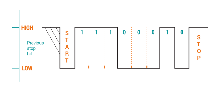
So what’s going on here? The solid line represents the logic levels and the orange dotted lines represent the sampling times, where the time between two consecutive dotted lines is a period, which is actually the inverse of the baud rate.
The Start Bit
You’ll notice that at the start of the transmission, the logic level is HIGH. This is the default logic level of the TX pin when not sending a message.
When the sender is ready to send information, it starts by bringing its TX pin LOW – this is the start bit. The receiver is on the lookout for this and when it sees the logic level go from HIGH to LOW on its RX pin, this state change tells the receiver “Hey, a message is about to come in!”.
The Receiver, based on the baud rate, then begins to read in the message one bit at a time that is coming in at its RX pin. The Receiver waits one and a half cycles to start sampling the line after it sees the initial state change.
Why does it wait one and a half cycles, and not just one cycle? Well, by waiting 1 and a half cycles, it is able to sample right in the middle of the incoming signal. So it can be sure what it reads is the correct signal.
Say you are pounding nails into studs to hang drywall – you want to get your nail right into the center of the stud to get the best quality connection. The receiver wants to sample right in the middle of the transmission to get the best guarantee that what it measured was the true signal.
The message AKA Data Frame
Referring back to the diagram above, now the Receiver is actually reading in the message. The message portion of the transmission is called the data frame. The first time it samples, the logic level is HIGH. If you imagine the Receiver being some guy with a clipboard, he’d be like, “Hey, let me mark a 1 down.”
The next time the Receiver samples, it’s still HIGH. That’s another 1.
After that, it’s still HIGH, that’s another 1.
Then it goes LOW, the Receiver would read that in as a 0.
And this keeps up for 8 bits. You’ll notice that the order of bits in the capital G is reversed – this is because the serial protocol sends the least significant bit first. This is how it was done long ago to confuse people like me.
Well OK, I’m sure there is some valid reason for sending the least significant bit first, but hey – it’s still confusing even when you know it.
The Parity Bit
Next comes an optional parity bit.
The default serial communication protocol for Arduino using Serial.begin() does not send a parity bit, but we’ll talk about it shortly, because I think it is pretty neat.
The term parity refers to whether a number is even or odd. If you asked me the parity of the number 12, the answer would be even.
Having a parity bit is a way for the receiver to check if the information received in the data frame was corrupted – that is, parity bits are for error checking.
When a parity bit is used, both the sender and receiver agree ahead of time on either even or odd parity. The parity is determined by counting the number of bits with the value 1 in the data frame including the parity bit. Now I know that sounds super confusing, but it is deceptively simple.
Say for example, the sender and receiver agree to have an even parity. This means all the 1’s in the data frame PLUS the parity bit need to equal an even number.
So if the data frame has three 1s, then the sender will set the parity bit to a 1 as well – this way, the total number of ones is 4, which has even parity.
Serial Communication parity examples
Even parity example – transmission free of errors
Data Frame | Parity Bit is set to 1, to make the total of all 1s an even number
0001 1100 1 4 ones total, 4 is even -> this checks good
Even parity example – error!
Data Frame | Parity Bit is set to 1, to make the total of all 1s an even number
0001 1101 1 5 ones total, 5 is odd -> error – should be an even number
If the receiver counts up all the 1’s in the transmission, and finds that it doesn’t match the agreed upon even parity, then it knows that something has corrupted the data frame, and perhaps it can ask for that data frame again.
The Stop Bit
When the last bit of the data frame or the parity bit is sent, the sender then sets its TX pin HIGH, this is the stop bit. The stop bit is always HIGH. And the TX pin will stay HIGH until the start bit of the next transmission brings it LOW and starts the whole process over again.
The Baud Rate is SUPER important
Notice that the baud rate is super important. If the Sender is sending at a slow baud rate, and the Receiver is reading at a fast baud rate – it would be total mayhem. The message the Sender would read would be all messed up.
The baud rate is how many times per second the signal could change. If you set a baud rate of 9600, that means the signal could change once every 1 / 9600 = 0.00010416666 seconds.
A quick rule of thumb to calculate the bytes per second, is to divide the baud rate by the total number of bits sent in one packet.
With one start bit, 8 data bits, and a stop bit we have a total of 10 bits. With a baud rate of 9600 you can send 960 bytes per second.
The baud rate is going to tell the sender when to send, and the receiver when to sample.
When using the Arduino Serial library, you set the baud rate with the Serial.begin() function. The baud rate is the value that goes inside the parentheses.
Programming Electronics Academy members, learn how to choose, install, and use Arduino libraries in the Arduino Course for Absolute Beginners Code Libraries section.
Not a member yet? Sign up here.
What’s so special about 9600?
You might be wondering what’s the significance of 9600? Can you change that or will your Arduino blow up?
First, yes, you change the baud rate and your Arduino will NOT blow up – you just need to make sure that the baud rate of both devices are the same.
Why the 9600? Well, there are simply conventional baud rates out there. There is no good reason not to use a faster baud rate, like say 115200. It’s just that 9600 is pretty adequate for most serial communication done with an Arduino.
If something is a convention, it just means what everybody kind of does and expects others to do.
Like, let’s say you’re driving on a highway in the USA, you’ll often see a speed limit sign of 65 mph.
If you’re in Canada it might be something like 100 km/h.
I mean, they could make it a 63 MPH speed limit, or a 97.2 km/h, but…that’d be weird – because it doesn’t follow convention.
OK – weird is a good stopping point.
Serial Communication Review:
- Serial communication works by sending one bit at a time
- There are many forms of serial communication, and most Arduino come equipped to several different kinds
- One of the simplest forms of serial communication is between USARTs, and is often referred to as TTL serial
- Both the sender and the receiver need to agree on the timing of the signal – this is called the baud rate
- The common baud rate of 9600 is just a convention
Well hey, I hope you found this helpful! If you’re curious about other features of the serial communication, make sure to check our other lessons!
This is just the tip of the iceberg!






I’m interested in setting up comms between an arduino and a raspberry pi. My problem is, all the examples I can find use Python I want use C++ do any of your courses cover this?
Thanks
Great questions Richard, We currently do not have a course on interfacing RaspPi with Arduino. Not sure exactly what kind of comms you want to set up, but just installing the Arduino IDE on the RaspPi, and using out of the box Arduino serial library communication might be the simplest method. Best of luck!
I cannot seem to find this on my members page
The black dots?
https://www.programmingelectronics.com/serial-communication/#:~:text=levels%20and%20the-,black%20dots,-represent%20the%20sampling
Thank you Gerrit. Corrected.