
Arduino Solar Power Control System :: Member Project
When Ray Johnson installed his new solar electric system, he was excited about the ability to implement this to use solar energy for his home.
However, he was in for a sunny surprise when he discovered that he either did not have enough solar energy to supply the loads he had connected or had an excess of solar energy that was going to waste.
But Ray didn’t let this stop him at all! He decided to come up with an Arduino power control system that allowed him to have more control over just how the rays of sunshine he collected went to powering his home. Take a look below at his radiant creation!

Hi Ray! So, tell us about your project.
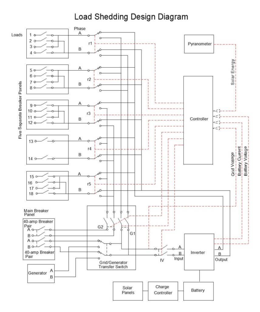
I designed a control system that will provide load shedding/load leveling.
The controller continually examines the amount of solar energy available and connects or disconnects loads such that the maximum amount of available solar power is being used, and thus minimizes the use of grid power, protects the battery bank from being too deeply discharged, and lengthens the battery life.
Whoa, wait a minute. What a cool idea! Why did you decide to build this?
In 2017, I purchased a 4400-watt two-phase solar electric system that could generate enough electric power to power my entire household whenever solar energy was available.
It consisted of 12 solar panels, 12 AGM batteries, an inverter, a charge controller for the batteries, and a system controller.
Unlike the more typical solar systems currently being installed, which simply generate power to be sold back to the utility company, this system was designed to provide household power even in the event of a grid power failure.
However, the delivery system did not give me sufficient control to avoid a lot of ongoing human interaction to operate the system. So, I elected to design my own controller as a ‘front end’ to the system.
That’s some great innovation there! So, tell us more about how your project works?
Well, the controller allows the optimal electrical load to run on solar power. When solar energy is not available (such as at night) all loads are normally connected to grid power and, if necessary, the batteries are recharged from grid power.
Five relays (dubbed R1 through R5) switch their respective two-phase loads between solar and grid power. Relays R1 and R2 are used to remove grid power from the load group for a fraction of a second when they are being toggled.
This prevents the possibility of creating an arc between solar and grid power.
The inverter is programmed in a mode called Auto Connect. When grid power is available at the inverter input, inversion ceases and the inverter is bypassed, powering any solar loads directly from the grid.
Thus, R4 controls the presence or absence of grid voltage at the inverter input. All eight relays are also controlled by the Controller.
There is also a timer running in the background which interrupts the loop code every minute. If any major changes in the system state have occurred since the last interrupt, appropriate action is taken.
Every 15 minutes, the solar conditions are re-evaluated, and an additional load group is placed on solar power if sufficient solar power is available, one load group is removed and placed on grid power if not, or the load is left unchanged.
Wow, that’s amazing. Can you elaborate a bit on all this information being sent to the Controller?
Inputs to the Controller consist of the following measurements: grid voltage, battery voltage, battery current, and solar energy.
The grid voltage is measured to sense grid power failures. Battery voltage I measured to sense the battery condition. Battery current is measured to sense if the battery is being charged or discharged.
Available solar energy is measured by a pyranometer.
Such a plethora of information being sent to the Controller! How exactly do you, well, control the Controller?
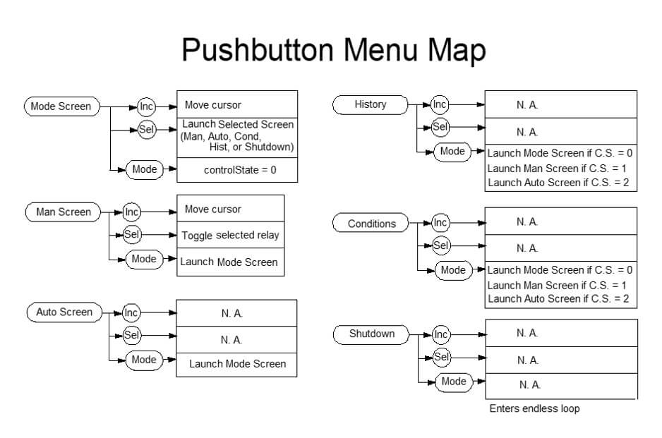
Operating the Controller is done via three pushbutton switches. These pushbuttons create hardware interrupts.
Thus, the loop code consists of continually checking for interrupt flags and taking appropriate actions. The MODE button allows the user access to all of the available screens.
The INCrement button allows the user to choose between the various options shown on the current screen. For example, in the MODE screen, the user chooses another screen that they desire to view.
In the MAN screen, the user chooses which relay he wishes to toggle. The SELect button allows the user to select the choice made via the INC button.
Wow! Could you also tell us more about how the users interact with your program?
Six different LCD screens are available to the user. In the MAN screen, the eight relays are directly controlled.
This MANual mode is intended only for handling problem conditions that could occur. The AUTO screen displays the load groups currently being powered by solar.
The intent is that the controller will remain in this mode without human intervention for very long periods of time (months). It is designed to handle the presence or absence of grid power, low battery conditions, etc., without human intervention.
The other screens are the CONDition screen in which current system conditions are displayed, the HISTory screen showing the number of load groups that have been connected to solar power during the last 10 hours, the SHUTDOWN screen that provides a well-behaved shutdown procedure, and the MODE screen which allows the user to switch between different screens.
So, if there is a manual mode, can you talk about how the AUTO mode works as well?
The AUTO mode is where the controller is intended to operate essentially all the time, without interruption, without regard to variations in operating conditions. It is designed to operate in a variety of conditions.
The three basic system parameters are
- The presence or absence of Grid Power.
- The presence or absence of Solar Energy.
- The battery voltage condition, whether above or below desired levels.
Every 15 minutes the auto mode routine is executed.
If solar is available, the controller decides whether to add or remove a load group from solar or to leave the load as is, based on whether the batteries are currently being charged or discharged. That way, the use of solar power is maximized without needlessly discharging the batteries.
Every minute, system conditions are examined to see if any of the three basic system parameters have changed. If so, auto mode is executed and the 15-minute cycle clock is reset.

Were there some aspects of this project that you struggled with?
Well, the simplicity of the operation of this device does come at a cost.
The software which implements all the various possibilities of pushbutton combinations is quite involved and required about 800 lines of Arduino/C++ code.
Congratulations on completing such a task! What other components did you use in your project?
The controller is implemented by an Arduino MEGA2560 microcomputer programmed in Arduino/ C++ language.
It consists of the MEGA2560, a 40 character by 4-line LCD display, three push buttons, an on/off switch, and all of the necessary signal conditioning and interface circuitry.
Arduino code:
Ray was kind enough to share his source code with us. You can see his code listed below:
//This sketch implements the software-based, LCD version of the solar controller.
//Written by M. Ray Johnson, Beginning August 2018 until April 2019. This algorithm assumes the Inverter is
//placed in the AUTO CONNECT mode.
//UPDATES:
//18March2019: Eliminated all unnecessary relay closures and increased the cycle time to 15 minutes to increase
//relay life.
#include <TimerOne.h>
#include <LiquidCrystal.h> //set up the LCD
const int RS=12, E1=11, E2=10, D4=7, D5=6, D6=5, D7=4;
LiquidCrystal lcd1(RS, E1, D4, D5, D6, D7); //top two lines of display
LiquidCrystal lcd2(RS, E2, D4, D5, D6, D7); //bottom two lines of display
volatile boolean incFlag = LOW; //declare variables used in ISRs
volatile boolean selFlag = LOW;
volatile boolean modeFlag = LOW;
volatile boolean timerFlag = LOW;
volatile boolean currentSolarState = LOW;
volatile boolean currentGridState = LOW;
volatile boolean currentBatState = LOW;
volatile boolean changeFlag = LOW;
volatile boolean cycleFlag = LOW; //LOW indicates vB has dropped to vBminLow;
volatile boolean vBflag = HIGH; //HIGH indicates vB has risen to vBminHigh.
volatile boolean oldSolarState = LOW;
volatile boolean oldGridState = LOW;
volatile boolean oldBatState = LOW;
volatile boolean incEnable = LOW; //LOW disables inc button interrupts
volatile boolean selEnable = LOW;
volatile boolean timerEnable = LOW;
volatile boolean relayState[] = {HIGH, HIGH, HIGH, HIGH, HIGH, HIGH, HIGH, HIGH}; //HIGH indicates de-energized.
//For the LG relays, HIGH indicates the load is
volatile byte manCursorPos = 0; //connected to GRID power; LOW to SOLAR power.
volatile byte index = 0; //For G1 and G2, HIGH indicates a closed condition,
volatile byte mode = 0; //connecting their respective LGs to GRID. For
volatile byte horizCursorPos = 0; //the IV relay, HIGH indicates a closed condition,
volatile byte solarLoadCount = 0; //connecting Grid power to the inverter input.
volatile byte loadStateHistory[] = {0,0,0,0,0,0,0,0,0,0,0,0,0,0,0,0,0,0,0,0,0,0,0,0,0,0,0,0,0,0,0,0,0,0,0,0,0,0,0,0};
volatile byte controlState = 0;
volatile byte manIndex = 0;
volatile int powerSources = 0;
volatile int minutes = 0;
volatile int sixSec = 0;
int iBint = 0;
int vBint = 0;
volatile float iB = 0.0;
volatile float pyra = 0.0;
volatile float vB = 0.0;
volatile float vG = 0.0;
volatile int vDir = 0;
volatile int iDir = 1;
volatile unsigned int eventTime = 0;
const float pyraMin = 0.4;
const float vGmin = 100.0;
const float vBminHigh = 53.0;
const float vBminLow = 48.0;
String man1 = "MANUAL MODE"; //LCD screen string arrays
String man2 = "Control load group relays as desired";
String man3 = "LG1 LG2 LG3 LG4 LG5 G1 G2 IV ";
String man4 = " ";
String man6 = "All loads on Grid Power ";
String man7 = "IV cannot open until all LGs are on GRID";
String man10 = "All loads are without power"; //manSelect are relay state labels
String manSelect[] = {"GRID ","GRID ","GRID ","GRID ","GRID ", "CLO ", "CLO ", "CLO "};
String mode1 = "MODE SELECT";
String mode2 = "Select one of the following modes";
String mode3 = "MAN AUTO COND HIST SHUTDWN";
String auto1 = "AUTO MODE";
String auto3 = "Grid and Solar Power are available ";
String auto4 = "Grid Power failure; Solar is available ";
String auto5 = "Grid Power is available; Solar is not ";
String auto6 = "Grid Power failure; Solar not available ";
String auto7 = "Load Group(s) on Solar: ";
String auto15 = "Battery Low";
String menu5 = "CURRENT CONDITIONS";
String shutdwn1 = "PLEASE WAIT";
String shutdwn2 = "PLEASE TURN THE CONTROLLER OFF NOW";
String history1 = "SOLAR LOAD HISTORY";
const byte relay1 = 22; //Load Group 1 relay LOW is SOLAR (energized)
const byte relay2 = 23; //Load Group 2 relay
const byte relay3 = 24; //Load Group 3 relay
const byte relay4 = 25; //Load Group 4 relay
const byte relay5 = 26; //Load Group 5 relay
const byte relayG1 = 27; //Grid relay for Load Groups 1,2. LOW is open (energized)
const byte relayG2 = 28; //Grid relay for Load Groups 3,4,5. LOW is open (energized)
const byte relayIv = 29; //Inverter Input relay. LOW is open (energized)
const byte batCurrent = A10; //Battery Current 0 to 1023 counts = -25 to +25 amps. Was A4
const byte pyranometer = A7; //0 to 5.0 VDC signal. Was A0
const byte batVoltage = A8; //0 to 66.7 VDC. Was A2
const byte gridVoltage = A9; //5.12 VDC corresponds to 125 VAC (RMS). Was A3
const int arcDelayPeriod = 20; //current arc delay period in ms
//Analog input A1 is apparently faulty. Move all analog
//inputs to A7 thru A10
void setup() {
Serial.begin(9600); //enable the computer serial monitor
lcd1.begin(40,2); // set up the LCD's number of columns and rows:
lcd2.begin(40,2);
pinMode(4, OUTPUT); //Define digital I/O, LCD data and control lines
pinMode(5, OUTPUT);
pinMode(6, OUTPUT);
pinMode(7, OUTPUT);
pinMode(11, OUTPUT);
pinMode(10, OUTPUT);
pinMode(12, OUTPUT);
pinMode(relay1, OUTPUT); //Relay control lines - Load Group 1 Relay
pinMode(relay2, OUTPUT); //LG2 Relay
pinMode(relay3, OUTPUT); //LG3 Relay
pinMode(relay4, OUTPUT); //LG4 Relay
pinMode(relay5, OUTPUT); //LG5 Relay
pinMode(relayG1, OUTPUT); //G1 Relay
pinMode(relayG2, OUTPUT); //G2 Relay
pinMode(relayIv, OUTPUT); //IV Relay
pinMode(pyranometer, INPUT); //Define analog inputs. 0 to 5.0 VDC signal
pinMode(gridVoltage, INPUT); //0 to 125 VAC (RMS)
pinMode(batVoltage, INPUT); //0 to 60 VDC
pinMode(batCurrent, INPUT); //-25 to +25 amps
attachInterrupt(digitalPinToInterrupt(2), isrMode, RISING); //set up 1st priority interrupt (Mode, on pin 2)
attachInterrupt(digitalPinToInterrupt(3), isrIncrement, RISING); //set up 2nd priority interrupt (Inc, on pin 3)
attachInterrupt(digitalPinToInterrupt(18), isrSelect, RISING); //set up 3rd priority interrupt (Select, on pin 18)
Timer1.initialize(6000000); //set up 4th priority interrupt (Timer, every 6 sec)
Timer1.attachInterrupt(isrTimer);
modeScreen(); //launch the mode screen
digitalWrite(relayG1, LOW); //open G1
digitalWrite(relayG2, LOW); //open G2
delay(arcDelayPeriod);
digitalWrite(relayIv, HIGH); //close IV
relayState[7] = HIGH;
manSelect[7] = "CLO ";
for(byte i = 0; i < 5; i++) { //de-energize all Load Group relays [This leaves all Load Group Relays
digitalWrite(22 + i, HIGH); //in the GRID position, and G1, G2, and IV closed.
relayState[i] = HIGH;
manSelect[i] = "GRID ";}
delay(arcDelayPeriod);
digitalWrite(relayG1, HIGH); //close G1
relayState[5] = HIGH;
manSelect[5] = "CLO ";
digitalWrite(relayG2, HIGH); //close G2
relayState[6] = HIGH;
manSelect[6] = "CLO ";
modeFlag = LOW; //reset all the interrupt flags
incFlag = LOW;
selFlag = LOW;
timerFlag = LOW;
cycleFlag = LOW;
solarLoadCount = 0;
index = 0;
manIndex = 0;
horizCursorPos = 0;
manCursorPos = 0;
checkStateChange(); //initialize the change state conditions
oldSolarState = currentSolarState;
oldGridState = currentGridState;
oldBatState = currentBatState;
changeFlag = LOW;
vBflag = HIGH;
minutes = 0;
for(int i = 0; i < 40; i++) { //initialize history
loadStateHistory[i] = 0;}
controlState = 0; } //end of setup
void loop() {
if(modeFlag == HIGH) { //check to see if Mode Button has been pressed
delay(300); //debounce
modeFlag = LOW;
if(mode == 0) { //if I'm in mode screen
controlState = 0;
modeScreen();
return;}
else if(mode == 1) { //if I'm in man screen
manCursorPos = horizCursorPos; //save the cursor position
manIndex = index;
modeScreen();
return; }
else if(mode == 2) { //if I'm in auto screen
modeScreen();
return; }
else if(controlState == 0) { //if I'm in no control
modeScreen();
return; }
else if(controlState == 1) { //if I'm in man control
horizCursorPos = manCursorPos; //restore the cursor position
index = manIndex;
manMode();
return; }
else { //I'm in auto control
autoMode();
return; } }
else if(incFlag == HIGH) { //check to see if Increment Button has been pressed
delay(300); //debounce
incFlag = LOW;
if(mode == 0) { //if I'm currently in Mode screen
if(horizCursorPos < 28) { //move the cursor in the Mode screen
horizCursorPos += 7;}
else horizCursorPos = 0;
lcd2.setCursor(horizCursorPos,0); //reposition the cursor
index = horizCursorPos/7; //point to the current menu item
return; }
else { //I'm currently in Man screen
if(horizCursorPos < 35) { //move the cursor in the Man screen
horizCursorPos += 5;}
else horizCursorPos = 0;
lcd2.setCursor(horizCursorPos,1); //reposition the cursor
index = horizCursorPos/5; //point to current relay
return; } }
else if(selFlag == HIGH) { //check to see if the Select Button has been pressed
delay(300); //debounce
selFlag = LOW;
if(mode == 0) { //if I'm in the mode screen
if(index == 0) { //if Man Mode has been selected
horizCursorPos = manCursorPos; //restore the cursor position
index = manIndex;
manMode(); //launch manMode
return; }
else if(index == 1) { //if Auto Mode has been selected
minutes = 0; //start the cycle clock
if(solarLoadCount > 0) { //adjust IV according to solarLoadCount
if(relayState[7] == HIGH) { //if IV is closed, open it
relayState[7] = LOW;
manSelect[7] = "OPEN ";
digitalWrite(relayIv, LOW); } }
else {
if(relayState[7] == LOW) { //if IV is open, close it
relayState[7] = HIGH;
manSelect[7] = "CLO ";
digitalWrite(relayIv, HIGH); } }
autoMode(); //launch autoMode
return; }
else if(index == 2) { //if Conditions Mode has been selected
conditionsScreen(); //launch conditionsScreen
return; }
else if(index == 3) { //History Mode has been selected
historyScreen(); //launch history screen
return; }
else { //Shutdown has been selected
shutdwnScreen(); //launch shutdown screen
return;} }
else { //I'm currently in the Man screen
manToggle();
manCursorPos = horizCursorPos; //save the cursor position
manIndex = index;
return;} }
else if(timerFlag == HIGH) { //check timer flag
timerFlag = LOW;
if(sixSec >= 10){
sixSec = 0;
checkVbFlag();
checkStateChange();
if(mode == 4) conditionsScreen();
if(mode == 5) historyScreen();
if(changeFlag == HIGH) { //if the system state has changed
Serial.print("State change detected. Time = ");
eventTime = millis()/60000;
Serial.println(eventTime);
Serial.print("vB = ");
Serial.println(vB);
Serial.print("pyra = ");
Serial.println(pyra);
Serial.print("vG = ");
Serial.println(vG);
if(mode == 2) goto t1;
else if(mode == 1) {
manMode();
return; }
else return; }
else if(controlState != 2) return;
else {
printCycle(); //update the cycle display
if(minutes >= 15) { //if 15 minutes have passed
t1: cycleFlag = HIGH;
minutes = 0;
updateHistory();
autoMode();
return; }
else {
minutes ++;
return;} } }
else {
sixSec ++;
return;} }
else return; } //end of loop
//*****PUT CALLED FUNCTIONS HERE*****
void modeScreen(void) { //This function clears the display, then creates the Mode Screen
lcd1.clear();
lcd2.clear();
lcd1.setCursor(0,0);
lcd1.print(mode1); //print "MODE SELECT" on LCD line 1
lcd1.setCursor(0,1);
lcd1.print(mode2); //print LCD line 2
lcd2.setCursor(0,0);
lcd2.print(mode3); //print LCD line 3
lcd2.setCursor(0,0); //turn on the blinking cursor
lcd2.cursor();
lcd2.blink();
horizCursorPos = 0;
index = 0;
mode = 0;
selEnable = HIGH; //enable select interrupts
incEnable = HIGH; //enable increment interrupts
timerEnable = LOW; //disable timer interrupts
return; } //end of modeScreen
void conditionsScreen(void) { //This function clears the dsplay, then creates the
lcd1.clear(); //Conditions Screen.
lcd2.clear();
lcd1.noCursor();
lcd1.noBlink();
lcd2.noCursor();
lcd2.noBlink();
lcd1.setCursor(0,0);
lcd1.print(menu5); //"CURRENT CONDITIONS"
printConditions(); //print conditions on LCD lines 2 and 3
readPowerSources();
lcd2.setCursor(0,1); //print power sources on line 4
if(powerSources == 3) lcd2.print(auto3); //"Grid and Solar Power are available"
if(powerSources == 2) lcd2.print(auto4); //"Grid Power failure; Solar is available"
if(powerSources == 1) lcd2.print(auto5); //"Grid Power is available; Solar is not"
if(powerSources == 0) lcd2.print(auto6); //"Grid Power failure; Solar not available"
selEnable = LOW; //disable Select Button interrupts
incEnable = LOW; //disable Increment Button interrupts
timerEnable = HIGH; //enable timer interrupts
mode = 4;
return; } //end of Conditions Screen
void historyScreen(void) { //This function clears the display, then creates the
lcd1.clear(); //History Screen.
lcd2.clear();
lcd1.setCursor(0,0);
lcd1.print(history1); //"SOLAR LOAD HISTORY" on line 1
lcd1.noCursor();
lcd1.noBlink();
lcd2.noCursor();
lcd2.noBlink();
printHistory(); //print the load history on LCD line 4
readPowerSources();
lcd2.setCursor(0,1); //print power sources on line 4
if(powerSources == 3) lcd2.print(auto3); //"Grid and Solar Power are available"
if(powerSources == 2) lcd2.print(auto4); //"Grid Power failure; Solar is available"
if(powerSources == 1) lcd2.print(auto5); //"Grid Power is available; Solar is not"
if(powerSources == 0) lcd2.print(auto6); //"Grid Power failure; Solar not available"
selEnable = LOW; //disable Select Button interrupts
incEnable = LOW; //disable Increment Button interrupts
timerEnable = HIGH; //enable timer interrupts
mode = 5;
return; } //end of historyScreen
void shutdwnScreen(void) { //This function provides for a well-behaved
lcd1.clear(); //shutdown process that creates the Shutdown
lcd2.clear(); //screen, de-energizes all relays, invites the
lcd2.noCursor(); //user to turn off the controller, and enters
lcd2.noBlink(); //an endless loop.
boolean b = LOW; //avoid unnecessary relay actions
for(int a = 2; a < 5; a++) {
if(relayState[a] == LOW) b = HIGH; }
if(b == HIGH) {
digitalWrite(relayG1, LOW); //Open G1
delay(arcDelayPeriod);
for(int q = 0; q < 5; q++) {
if(relayState[q] == LOW) {
solarLoadCount--;
digitalWrite(q + 22, HIGH);
relayState[q] = HIGH;
manSelect[q] = "GRID "; } }
delay(arcDelayPeriod);
digitalWrite(relayG1, HIGH); } //Close G1
digitalWrite(relayIv, HIGH); //close IV
selEnable = LOW; //disable select interrupts
incEnable = LOW; //disable increment interrupts
timerEnable = LOW; //disable timer interrupts
s1: lcd1.setCursor(0,0);
lcd1.print(shutdwn2); //LCD line 1: "PLEASE TURN THE CONTROLLER OFF NOW"
delay(1000);
lcd1.clear();
delay(300);
goto s1; //endless loop
return; } //end of Shutdown Screen
void manMode(void) { //This function implements the Manual Mode. It
mode = 1; //creates the appropriate screen depending on
controlState = 1; //conditions.
incEnable = HIGH; //enable Increment Interrupts
selEnable = HIGH; //enable Select Interrupts
timerEnable = HIGH; //enable Timer Interrupts
readPowerSources();
lcd1.clear();
lcd2.clear();
lcd1.setCursor(0,0);
lcd1.print(man1); //"MANUAL MODE" on line 1
lcd1.setCursor(0,1); //print power sources on line 2
if(powerSources == 3) lcd1.print(auto3); //"Grid and Solar Power are available"
if(powerSources == 2) lcd1.print(auto4); //"Grid Power failure; Solar is available"
if(powerSources == 1) lcd1.print(auto5); //"Grid Power is available; Solar is not"
if(powerSources == 0) lcd1.print(auto6); //"Grid Power failure; Solar not available"
lcd2.setCursor(0,0);
lcd2.print(man3); //"LG1 LG2 LG3 LG4 LG5 G1 G2 IV "
lcd2.setCursor(0,1);
for(int p = 0; p < 8; p++) { //print current relay states on line 4
lcd2.print(manSelect[p]); }
lcd2.setCursor(horizCursorPos,1); //put the cursor back where it was
lcd2.cursor();
lcd2.blink();
checkVbFlag();
if(vBflag == HIGH) {
lcd1.setCursor(28,0); //clear the "battery Low" message
lcd1.print(" "); }
else {
lcd1.setCursor(28,0);
lcd1.print(auto15); } //Print "Battery Low" message
return; } //end of manMode
void autoMode(void) { //This function implements the Auto Mode
Serial.print("AUTO Mode executed. Time = ");
eventTime = millis()/60000;
Serial.println(eventTime);
incEnable = LOW; //disable increment interrupts
selEnable = LOW; //disable select interrupts
timerEnable = HIGH; //enable timer interrupts, for 5 minute load checks.
checkVbFlag(); //This function executes every five minutes or
mode = 2; //sooner if gross system conditions change.
controlState = 2;
if(manSelect[5] = "OPEN ") { //if G1 is open, close it. This is in case some
relayState[5] = HIGH; //idiot left G1 or G2 open when leaving MAN mode.
manSelect[5] = "CLO ";
digitalWrite(relayG1, HIGH); }
if(manSelect[6] = "OPEN ") { //if G2 is open, close it.
relayState[6] = HIGH;
manSelect[6] = "CLO ";
digitalWrite(relayG2, HIGH); }
lcd1.clear(); //clear the auto mode Screen
lcd2.clear();
lcd1.setCursor(0,0);
lcd1.print(auto1); //print "AUTO MODE" on LCD line 1
horizCursorPos = 0;
lcd2.noCursor(); //turn off the blinking cursor
readPowerSources();
lcd2.noBlink();
lcd1.setCursor(0,1); //print power sources on line 2
if(powerSources == 3) lcd1.print(auto3); //"Grid and Solar Power are available"
if(powerSources == 2) lcd1.print(auto4); //"Grid Power failure; Solar is available"
if(powerSources == 1) lcd1.print(auto5); //"Grid Power is available; Solar is not"
if(powerSources == 0) lcd1.print(auto6); //"Grid Power failure; Solar not available"
if(vBflag == HIGH) {
lcd2.setCursor(0,1);
lcd2.print(man4); //clear the "Battery Low" message
if(powerSources >= 1) { //if either Grid or Solar power is available
if(cycleFlag == HIGH) { //if the cycle time is up
cycleFlag = LOW;
if(powerSources >= 2) { //if solar is available
adjustLoad();
if(solarLoadCount == 0) {
a3: lcd2.setCursor(0,0);
lcd2.print(man6); //print "All loads on GRID ..." on LCD line 3
a4: if(relayState[7] == LOW) { //close IV
relayState[7] = HIGH;
manSelect[7] = "CLO ";
digitalWrite(relayIv, HIGH); }
a5: printCycle(); //print cycle time
printIv(); //print IV relay state
return; }
else {
a6: if(relayState[7] == HIGH) { //open IV
relayState[7] = LOW;
manSelect[7] = "OPEN ";
digitalWrite(relayIv, LOW); }
a2: lcd2.setCursor(0,0);
lcd2.print(auto7); //print LCD line 3
solarLoadCount = 0; //print the load groups on solar
for (int q = 0; q < 5; q++) {
if(relayState[q] == LOW) {
solarLoadCount++;
lcd2.print(q + 1);
lcd2.print(" "); } }
goto a5; } }
else { //solar power is not available; put all load groups on Grid
a1: boolean b = LOW; //avoid unnecessary relay actions
for(int a = 2; a < 5; a++) {
if(relayState[a] == LOW) b = HIGH; }
if(b == HIGH) {
digitalWrite(relayG1, LOW); //Open G1
delay(arcDelayPeriod);
for(int q = 0; q < 5; q++) {
if(relayState[q] == LOW) {
digitalWrite(q + 22, HIGH);
relayState[q] = HIGH;
manSelect[q] = "GRID "; } }
delay(arcDelayPeriod);
digitalWrite(relayG1, HIGH); } //Close G1
solarLoadCount = 0;
if(powerSources == 1 || powerSources == 3) goto a3; //if Grid power is available
else {
lcd2.setCursor(0,0); //print LCD line 3, "All loads are without power" message
lcd2.print(man10);
goto a4; } } }
else goto a2; }
else { //put LG 1,2 on Solar; put LG 2,3,4 on Grid
if(relayState[0] == HIGH || relayState[1] == HIGH) { //avoid unnecessary relay actions
digitalWrite(relayG1, LOW); //Open G1
delay(arcDelayPeriod);
for(int q = 0; q < 2; q++) { //connect LG 1 and 2 to Solar
if(relayState[q] == HIGH) {
digitalWrite(q + 22, LOW);
relayState[q] = LOW;
manSelect[q] = "SOL "; } }
solarLoadCount = 2;
boolean b = LOW; //avoid unnecessary relay actions
for(int a = 2; a < 5; a++) {
if(relayState[a] == LOW) b = HIGH; }
if(b == HIGH) {
for(int q = 2; q < 5; q++) { //connect LG 3, 4, and 5 to Grid
if(relayState[q] == LOW) {
digitalWrite(q + 22, HIGH);
relayState[q] = HIGH;
manSelect[q] = "GRID "; } } }
delay(arcDelayPeriod);
digitalWrite(relayG1, HIGH); } //Close G1
goto a6; } }
else {
lcd2.setCursor(0,1);
lcd2.print(auto15); //Print "Battery Low" on LCD line 4
goto a1; } } //End of autoMode
//This function changes the state of the relay in the MAN display that has been selected for toggle.
//It switches the actual selected relay, and also syncs manSelect[] and RelayState[]. The global
//variable "index" points to the selected relay. If any of the LG relays are toggled, G1 or G2 will
//be opened momentarily to provide arc protection. Called only from manMode.
void manToggle(void) {
if(index < 2) { //if the selected relay is LG1 or LG2
if(manSelect[5] == "CLO ") { //if G1 is closed, open it
digitalWrite(relayG1, LOW);
delay(arcDelayPeriod);}
relayToggle(); //Toggle the relay
delay(arcDelayPeriod);
digitalWrite(relayG1, HIGH); //close G1
goto m1; }
else if(index < 5) { //if the selected relay is LG3, LG4, or LG5
if(manSelect[6] == "CLO ") { //if G2 is closed, open it
digitalWrite(relayG2, LOW);
delay(arcDelayPeriod);}
relayToggle(); //Toggle the relay
delay(arcDelayPeriod);
digitalWrite(relayG2, HIGH); //close G2
goto m1; }
else ctrlToggle(); //if the selected relay is G1, G2, or IV, toggle it
m1: lcd2.setCursor(0,0);
lcd2.print(man3); //reprint LCD line 3
lcd2.setCursor(0,1);
for(int p = 0; p < 8; p++) { //print current relay states on line 4
lcd2.print(manSelect[p]); }
lcd2.setCursor(horizCursorPos,1); //put the cursor back where it was
return; } //end of manToggle
void relayToggle(void) { //This function toggles the state of the load relays, LG1
if(manSelect[index] == "GRID ") { //through LG5, pointed to by the global pointer 'index'.
manSelect[index] = "SOL "; //manSelect, relayState and the actual relay are kept in sync.
relayState[index] = LOW; //It is called only from manToggle. This function DOES NOT
digitalWrite((22 + index), LOW); //provide arc protection which must be done in the calling
solarLoadCount++; } //function. solarLoadCount is also adjusted as needed.
else {
manSelect[index] = "GRID ";
relayState[index] = HIGH;
digitalWrite((22 + index), HIGH);
solarLoadCount--; }
return; } //end of relayToggle
void ctrlToggle(void) { //This function toggles the state of the control relay G1,
if(index > 6) { //G2 or IV, pointed to by the global pointer 'index'.
if(manSelect[7] == "OPEN ") { //manSelect, relayState and the actual relay are kept in
manSelect[7] = "CLO "; //sync. It is called only from manToggle.
relayState[7] = HIGH;
digitalWrite(relayIv, HIGH); }
else {
manSelect[7] = "OPEN ";
relayState[7] = LOW;
digitalWrite(relayIv, LOW); }
return; }
else if(manSelect[index] == "CLO ") { //Toggle either G1 or G2 pointed to by 'index'
manSelect[index] = "OPEN ";
relayState[index] = LOW;
digitalWrite((22 + index), LOW); }
else {
manSelect[index] = "CLO ";
relayState[index] = HIGH;
digitalWrite((22 + index), HIGH); }
return; } //end of ctrlToggle
void readPowerSources() { //This function identifies the current power
measureVg(); //sources (Grid and Solar) eturns the global
measureSolar(); //variable powerSources as follows:
if(vG > vGmin && pyra >= pyraMin) powerSources = 3; //0 = no power, 1 = grid power only,
else if(vG >= vGmin && pyra < pyraMin) powerSources = 1; //2 = solar power only, 3 = both grid and solar.
else if(vG < vGmin && pyra >= pyraMin) powerSources = 2;
else powerSources = 0;
return; } //end of readPowerSource
void adjustLoad(void) { //This function adjusts the number of load groups
measureIb(); //connected to solar power. It is called only from
if(iB > 0.0) { //function autoMode. Global variable solarLoadCount
if(solarLoadCount >= 5) return; //contains the number of load groups currently
else { //connected to solar power. Basis for the load
increaseLoad(); //adjustment is whether or not battery current is
return; } } //positive. If so, an attempt is made to add an
else if(solarLoadCount == 0) return; //additional Load Group to solar power. If not,
else { //a Load Group is removed.
decreaseLoad();
return; } } //end of adjustLoad
void increaseLoad(void) { //This function attempts to add an additional load group to
int i = -1; //Solar power. Loads are always added from relay1 to relay5.
c1: i++; //If solarLoadCount becomes greater than zero, IV is opened.
if(i > 4) return; //if all load groups have been tried
if(relayState[i] == LOW) goto c1 //if this LG relay is already connected to solar
if(i < 2) {
digitalWrite(relayG1, LOW); //Open G1
delay(arcDelayPeriod);
digitalWrite(i + 22, LOW); //add one load group to solar, relay1 or relay2
delay(arcDelayPeriod);
digitalWrite(relayG1, HIGH); } //Close G1
else {
digitalWrite(relayG2, LOW); //Open G2
delay(arcDelayPeriod);
digitalWrite(i + 22, LOW); //add one load group to solar, relay3, relay4, or relay5
delay(arcDelayPeriod);
digitalWrite(relayG2, HIGH); } //Close G2
manSelect[i] = "SOL ";
relayState[i] = LOW;
solarLoadCount ++;
if(relayState[7] == HIGH) { //if IV is closed, open it
relayState[7] = LOW;
manSelect[7] = "OPEN ";
digitalWrite(relayIv, LOW); }
return; } //end of increaseLoad
void decreaseLoad(void) { //This function disconnects one load group from solar.
int i = 5; //Loads are always deleted from relay5 to relay1. If
b1: i--; //solarLoadCount goes to zero, IV is closed.
if(i < 0) return;
if(relayState[i] == HIGH) goto b1;
if(i < 2) {
digitalWrite(relayG1, LOW); //Open G1
delay(arcDelayPeriod);
digitalWrite(i + 22, HIGH); //remove one load group from solar power, relay1 or relay2
delay(arcDelayPeriod);
digitalWrite(relayG1, HIGH); } //Close G1
else {
digitalWrite(relayG2, LOW); //Open G2
delay(arcDelayPeriod);
digitalWrite(i + 22, HIGH); //remove one load group from solar power, relay3, relay4, or relay5
delay(arcDelayPeriod);
digitalWrite(relayG2, HIGH); } //Close G2
delay(arcDelayPeriod);
manSelect[i] = "GRID "; //keep manSelect up to date
relayState[i] = HIGH; //keep relayState up to date
solarLoadCount --;
if(solarLoadCount == 0) { //if all loads have been connected to Grid power
if(relayState[7] == LOW) { //if IV is open, close it
relayState[7] = HIGH;
manSelect[7] = "CLO ";
digitalWrite(relayIv, HIGH); }
return; }
else return; } //end of decreaseLoad
void updateHistory(void) { //This function updates the load history array
for(byte m = 39; m > 0 ; m--) { //adding the latest value on the left and shifting
loadStateHistory[m] = loadStateHistory[m-1]; } //previous values to the right, retaining only the
loadStateHistory[0] = solarLoadCount; //latest 40 values (about 3 hours worth).
} //end of updateHistory
void printHistory(void) { //this function updates solar connection history on
lcd1.setCursor(0,1); //LCD line 2
for(byte z = 0; z < 40; z++) {
lcd1.print(loadStateHistory[z]); }
return; } //end of printHistory
void printCycle(void) { //This function prints the cycle time (min:sec) at
lcd1.setCursor(29,0); //the end of LCD line 1.
lcd1.print("cycle ");
lcd1.print(minutes);
return; } //end of printCycle
void printIv(void) { //This function prints the state of the IV relay on
lcd2.setCursor(27,1); //the end of LCD line 4.
lcd2.print(" ");
lcd2.setCursor(27,1);
lcd2.print("IVR = ");
if(relayState[7] == HIGH) lcd2.print("CLOSED");
else lcd2.print("OPEN");
return;} //end of printIv
void measureVg(void) { //This function measures Grid Voltage
int vGint = 0; //Take 5 readings and average them
for(int w = 0; w < 5; w++) {
vGint = analogRead(gridVoltage) + vGint;
delay(1);}
vG = float(vGint/31.10); //Gives value in VAC
return; }
void measureSolar(void) { //This function measures solar power availability
int pyraInt = 0; //Take 5 readings and average them
for(int x = 0; x < 5; x++) {
pyraInt = analogRead(pyranometer) + pyraInt;
delay(1);}
pyra = float(pyraInt)/1023.0;
//pyra = 1.0;
return; }
void measureVb(void) { //This function measures battery voltage
vBint = 0; //Take 5 readings and average them
for(int y = 0; y < 5; y++) {
vBint = analogRead(batVoltage) + vBint;
delay(1);}
vB = float(vBint)/85.2;
/*if(vDir == 1) { //for test purposes
vB = vB + 0.3;
if(vB > 54.0) vDir = 0; }
else {
vB = vB - 0.3;
if(vB < 46.0) vDir = 1; }*/
return; }
void measureIb(void) { //Range is roughly -25 amp to +25 amps over the range
iBint = 0; //Take 5 readings and average them. This is a very
for(int z = 0; z < 5; z++) { //noisy meassurement.
iBint = analogRead(batCurrent) + iBint;
delay(1); }
iBint = iBint/5; //0 to 1023. So zero current is about 512.
iBint = iBint - 512; //get to zero offset
iB = float(iBint) * 0.048828; //convert counts to amps
iB = (0.741 * iB) - 3.244; //conform to test data. The offset was
//iB = 1.0; //originally -4.444. I'm varying it to find
/*if(iBflag == 1) {
iB = iB + 0.2;
if(iB >= 1.0) iBflag = 0; }
else {
iB = iB - 0.2;
if(iB <= -1.0) iBflag = 1; }
Serial.print("iB = ");
Serial.println (iB);*/
return; } //the best balance.
void checkVbFlag(void) { //This function changes vBflag depending on the
measureVb(); //history of vB.
if(vB >= vBminHigh) vBflag = HIGH;
else if(vB < vBminLow) vBflag = LOW;
else return; }
void checkStateChange(void) { //this function checks the gross system state
measureSolar(); //(presence of solar, grid voltage, and high battery
checkVbFlag(); //voltage) and compares them with values last measured.
measureVg(); //If a major change has occured, changeFlag is set HIGH
if(pyra > pyraMin) currentSolarState = HIGH; //and the current LCD screen is updated to reflect these
else currentSolarState = LOW; //depending on the current mode. It is called only from
if(vG > vGmin) currentGridState = HIGH; //the code that services the timer ISR, and is typically
else currentGridState = LOW; //executed every minute if the timer interrupt is enabled.
if(vBflag == HIGH) currentBatState = HIGH;
else currentBatState = LOW;
changeFlag = LOW;
if(currentSolarState != oldSolarState) {
changeFlag = HIGH;
oldSolarState = currentSolarState; }
if(currentGridState != oldGridState) {
changeFlag = HIGH;
oldGridState = currentGridState; }
if(currentBatState != oldBatState) {
changeFlag = HIGH;
oldBatState = currentBatState; }
return; } //end of checkStateChange
void printConditions(void) { //this function measures current conditions and
measureVg(); //prints them on LCD lines 2 and 3
measureSolar();
measureVb();
measureIb();
lcd1.setCursor(0,1);
lcd1.print("Vg = ");
lcd1.print(vG,1);
lcd1.print(" Vb = ");
lcd1.print(vB,1);
lcd1.print(" IVR = ");
if(relayState[7] == HIGH) lcd1.print("CLOSED");
else lcd1.print("OPEN ");
lcd2.setCursor(0,0);
lcd2.print("Pyra = ");
lcd2.print(pyra,2);
lcd2.print(" Ib = ");
lcd2.print(iB,1);
return; } //end of printConditions
//*****PUT ISRs HERE*****
void isrMode(void) { //first priority ISR - Mode Button, never disabled
modeFlag = HIGH; }
void isrIncrement(void) { //second priority ISR - Increment Button
incFlag = incEnable; } //raise the interrupt flag if it is enabled
void isrSelect(void) { //third priority ISR - Select Button
selFlag = selEnable; } //raise the interrupt flag if it is enabled
void isrTimer(void) { //fourth priority ISR - Timer
timerFlag = timerEnable; } //raise the timer flag if it is enabled
Ray also included his design files for his project; check those out here:
Solar Power Controller Design File
Solar Power Controller Design File – Addeendum
About Ray:
Ray has a Ph.D. in Electrical Engineering, with experience programming in several different languages.
However, this is his first time programming in C++. He is an 80-year-old retiree who developed a newfound interest in Arduino as an affordable platform to accomplish his goals.






Wow Ray, that is impressive. I have been considering a similar unit for my solar setup, which is very similar to yours,1.8kw of PV panels, 48 volt 600Ahr battery and a 5kw inverter with built in MPPT charger. The one thing I want to do differently, is to switch an optional extra load into the circuit, if the batteries reach full charge with plenty of solar input still available, such as a small aircon unit on the battery box, or an ice maker. I also want to run two inverters, a smaller 500 watt or 1 kw unit when load conditions are light. I find the 5 kw inverter is drawing nearly 2 amps from the battery all night, even without a load at all, and this is a waste of solar/battery power,whereas a smaller inverter will draw proportionally less power at low loads.
This is awesome, I live in Australia and we get rebates from the government to put up solar on our roof. Any chance you will consider releasing the lot of it as open source code and hardware? I don’t remember seeing where you lived but if you had sun like us this system would be so much better than the 1/4 of the cost you get back from putting it in the grid. So we may pay $0.28 per kw and get $0.08 back
Hi Jay, we updated the post to include Rays code and his design write up. I hope this helps!
Very impressive Ray!! I have much of the set up (solar wise) as you but without any auto controls or computer monitoring. At 77, and with only a HS education, I’m not sure if I want to tackle such a project but mine might just be for monitoring purposes but still with manual control. Just getting started in Arduino and have never written code before so I’m not sure how far I can go with this. Thanks for the inspiration.
Please upload a video for this project