Arduino Transducer Tester :: Member Project
What better use of Arduino than to solve problems? One of our academy members, Nigel Moody, wanted to make sure that the transducers he was changing out at work were actually the source of the problem. (A transducer is essentially a sensor – it converts some form of energy into an electrical signal – so that the energy can be measured effectively.)
Nigel used an Arduino UNO to measure the output of the transducers, and then used an LCD to display that information in a readable fashion. Read on to find out more about Nigel’s transducer tester and how he made it.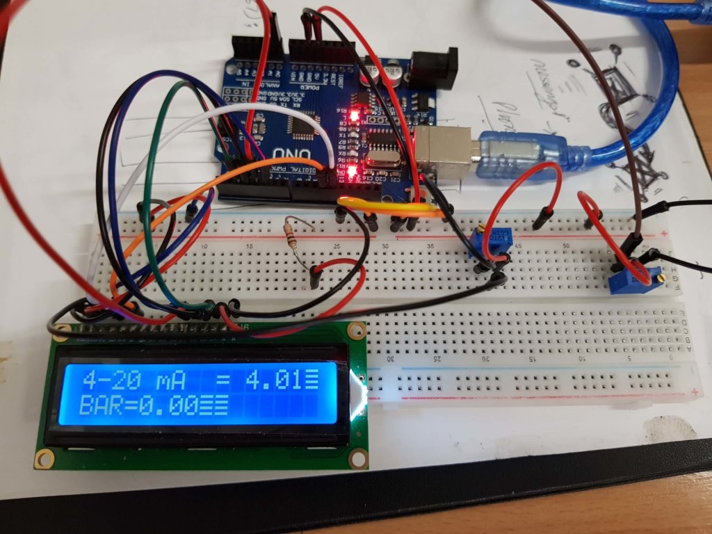
Nigel, why did you build an Arduino based transducer tester?
I had changed the sensor on the equipment I use at work, and there was no improvement to its operation, so I wanted to make something that I could use for work to test the performance of the equipment.
How does your project work?
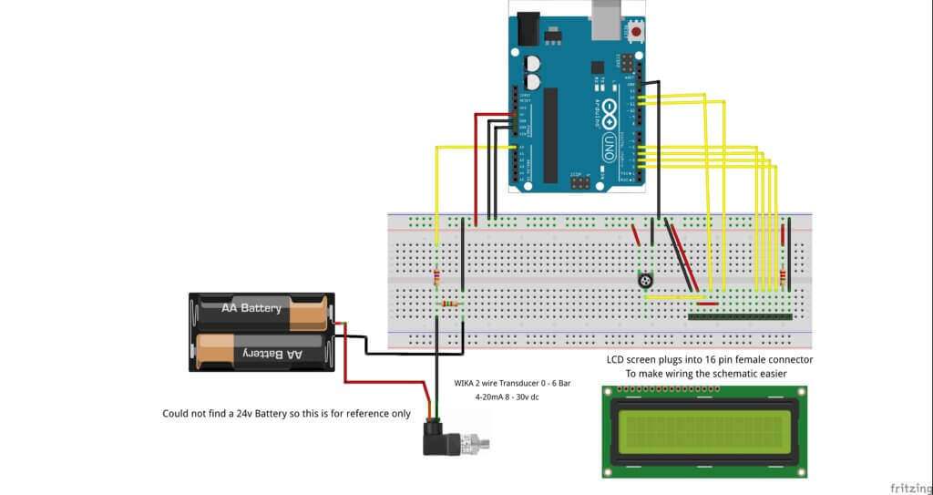
The sensor works on 8-30 volts DC, so I used 2 x 12-volt batteries. The Arduino can only accept 5-volt inputs, so I looked online for assistance.
I found out that I needed to control the current and voltage. The Arduino looks at the voltage and makes the required calculations to show volts, mA and BAR pressure.
What type of Arduino does your project use?
Arduino UNO Clone
What components did you use to make your project?
An LCD display, resistor, potentiometer, transducer 4-20Ma 2 wire 8-30 volts
How is your project powered?
Via USB from my computer, as well as through batteries
What was your biggest struggle working on this project?
My biggest struggle was getting the map function to work, but with some direction from your course, I was able to get the output values I wanted.
Editor’s Note: Nigel wanted the Arduino built-in map() function to output floating point numbers (i.e. numbers with decimal points) – but the built-in map function only does integer math (i.e. it rounds everything to whole numbers), so Nigel wrote his own user defined function float_map() to make it work like he wanted. Nice job Nigel!
Did the project end up as you expected?
Originally I was quite happy with simply being able to read the output on the serial monitor. But then I decided that if I wanted to be able to take the tester onto my job site, I would need a display.
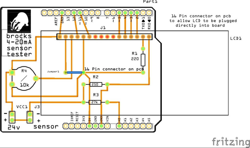
With a little more investigation, I linked up to a 16 x 2 LCD display. Now I will need to get another Arduino UNO and case to complete the project.
What can you say you have learned about programming and/or electronics through the creation process?
I have learned more about the way functions can be used and how to display the output on an LCD screen. I’ve also learned more about programming basics, which I started learning a while back, but stopped until now.
Arduino Code:
#include <LiquidCrystal.h>
LiquidCrystal lcd(12, 11, 5, 4, 3, 2);
/*
   To test a 4-20mA pressure sensor.
   voltage range 8-30 volt dc
   2 wire operation
*/
//set analogPin input pin
const int analogPin = A0;
//
int sensorValue = 0;
float bar = 0.0;
// float variables to use in calculation instead of
//the map function
float in_min = 1.0;
float in_max = 5.0;
float out_min = 0.0;
float out_max = 6.0;

void setup() {
  Serial.begin(9600);
  lcd.begin(16, 2);
}


void loop()
{
  // put your main code here, to run repeatedly:
  //variable sensorValue with analogRead
  sensorValue = analogRead(analogPin);

  //convert 0 - 1023 to 5 volts and make a float to
  // get a decimal
  //output.
  float voltage = sensorValue * (5.0 / 1023.0);
  // Serial print voltage output 0 - 5 volts
  Serial.print("Voltage     = ");
  Serial.println(voltage);
  //
  // Serial print senosorValue 0 - 1023
  Serial.print("sensorValue = ");
  Serial.println(sensorValue);
  //
  //Serial print mA output with conversion in decimal
  float mA = sensorValue * (20.0 / 1023.0);
  lcd.setCursor(0, 0);
  lcd.print("4-20 mA  = ");
  lcd.println(mA);
  // Use the second part of the map main calculation
  //after the return
  //bar = (voltage - in_min) * (out_max - out_min) / (in_max - in_min) + out_min;
  bar = float_map(voltage, in_min, in_max, out_min, out_max);
  lcd.setCursor(0, 1);
  lcd.noCursor();
  lcd.print("BAR=");
  lcd.println(bar);
  delay(1000);
  lcd.clear();


  if (mA<4){
  lcd.setCursor(11,1);
  lcd.print("FAULT");
  }
}
//
float float_map(float x, float in_min, float in_max, float out_min, float out_max) {
  return (x - in_min) * (out_max - out_min) / (in_max - in_min) + out_min;
}
About Nigel:
 Nigel is a Plumbing, Heating, and Refrigeration engineer. He first dabbled with electronics in school using an introductory kit, and he’s been tinkering with electronics most of his life. Nigel first tried programming basic when he was 26.
After starting a new project recently, he felt it would be worth it to pick up more programming skills, and came to Programming Electronics Academy to help him learn more.


[…] post Arduino Transducer Tester :: Student Project appeared first on Programming Electronics […]
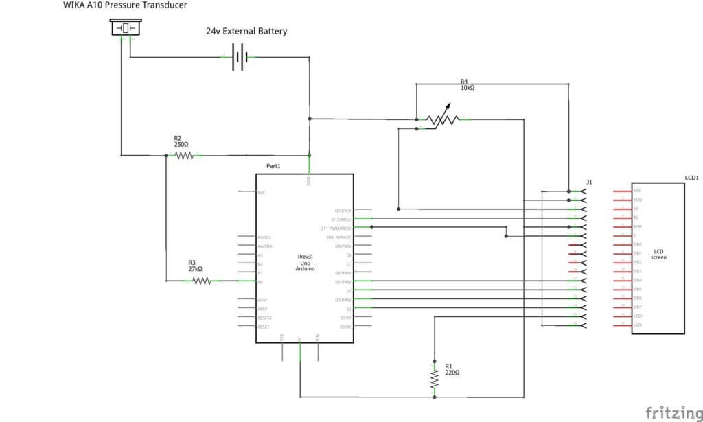
Can you provide a schematic to complement the Fritzing diagram?
Hello MonkeyBoy,
I have sent a schematic to be uploaded.
Nigel
Sure would like to know the function of the transducer he was troubleshooting. My mind thinks of a boat sonar, fish finder or lake bottom scanner.
Hello Randy A Perry
The transducer I was testing is a 0 – 6Bar Pressure transducer 2 Wire 8 -30 volt DC giving a 4-20mA output
Nigel
Looks intresting but I don’t understand the. Maths for working out bar .
Can you point me at something to explain it?
Hello Paul,
Maths is my weak point, but i will try and explain it the best I can.
The Arduino accepts an input voltage of 5 volts.
5 Divided by 20mA 5/20 = 0.25 volts per mA
The sensor only works from 4 to 20mA so that leaves 16mA .
16mA X 0.25 = 4 volts. So the map function was used to convert 1volt to give 4mA upto 5volts to give 20 mA
I had to change the map function to get it to deliver decimal points
First the variables
// float_map variables to use in calculation instead of
//the map function
float in_min = 1.0; //1 volt = 4 mA
float in_max = 5.0; //5 volt = 20mA
float out_min = 0.0;// 0 Bar
float out_max = 6.0; //6 Bar
and then the new map function which sits outside the loop.
float float_map(float x, float in_min, float in_max, float out_min, float out_max) {
return (x – in_min) * (out_max – out_min) / (in_max – in_min) + out_min;
I am very new to this so its all magic to me. :0)
PS Also when the Arduino detects a value lower than 4mA if flags up a broken wire fault on the real equipment so on mine it just says fault.
I am trying to on an SD card.make a setup to record pressure pulse up to transducer range 5000 psi, save the time dependent “spectrum” to display on oscilloscope. What is response time of the Arduino in this circuit configuration?
Hi Robert, Nigels code is using a 1 sec delay between readings. Not sure if this is what your asking? Or if you are trying to figure out how fast it *could* run, if you were to remove the delay?