The EASY guide to Over-the-Air (OTA) Updates With ArduinoOTA
Over-the-Air (OTA) updates allow you to upload code to your electronics project without needing it to be physically connected to a computer.
In this lesson, we’ll walk you through wirelessly uploading sketches to your ESP32 board using the ArduinoOTA library.

This guide is going to focus on just the minimum stuff you need to actually get over-the-air (OTA) updates to work..
You’ll learn about the key Arduino library you’ll need for making OTA super easy (ArduinoOTA) plus we’ll spell out the exact functions you’ll need to use!
Cables? Where we’re going we don’t need Cables!
Understanding ArduinoOTA for ESP32
Before we dive into the practical details, let’s first highlight what ArduinoOTA is and how it works specifically for ESP32.
ArduinoOTA (Over-The-Air) is a lightweight library that enables wireless sketch uploads to ESP32-based Arduino boards via a WiFi connection.
By utilizing this library in your Arduino projects, you can remotely update your sketches, eliminating the need for USB cables or any other wired connections and providing greater flexibility in deploying your projects wirelessly.
Programming Electronics Academy members, check out the Internet of Things (IoT) Course to start programming your own IoT devices.
Not a member yet? Sign up here.
A Case for the Over-The-Air Updates
The advantages of OTA programming with ESP32 are numerous.
It allows you to deploy ESP32-based projects in hard-to-reach locations or embed them in inaccessible devices after installation.
Furthermore, OTA programming enables rapid deployment of updates, saving valuable time and effort.
Getting Started with ArduinoOTA
To embark on the ArduinoOTA journey, you’ll need to install the required libraries and set up the hardware for a seamless process.
Ensure you have an ESP32 board, the Arduino IDE, and a stable WiFi connection before proceeding.
Once everything is ready, let’s move on to the next if getting the Arduino IDE setup.
Installing the Pre-requisites
To get started with installing the ArduinoOTA library and setting up the Arduino IDE for ESP32 boards (if you have not done that already).
First, let’s install the ESP32 board package:
- Open your Arduino IDE.
- Navigate to the Board Manager in the sidebar.
- Search for “ESP32” and select the esp32 by Espressif Systems.

- Allow some time for the installation process, which may vary based on your internet connection.

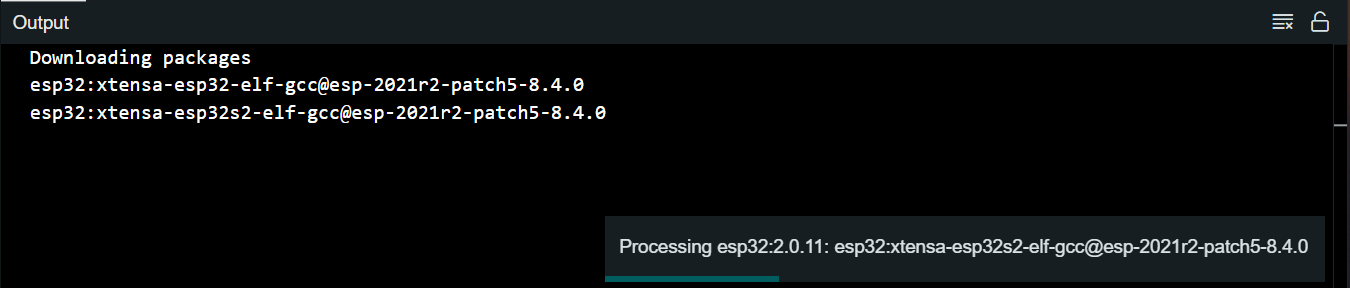
- Once completed, you’ll find the ESP32 board options in the Board Manager.
Now, let’s install the ArduinoOTA library.
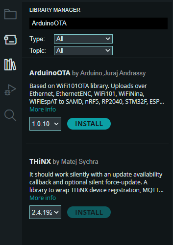
- Go to the Library Manager in the Arduino IDE.
- Search for ArduinoOTA, and install the library.
With the prerequisites, we’re ready to set up the hardware and establish the initial connection, as discussed in the next section.
Setting Up the Hardware
With the ESP32 board installed, connect it to your computer using a USB cable. Ensure the board is powered on and detected by the Arduino IDE.
Wait, what? We still need a physical connection?!
At this point, you might wonder if a physical connection is still necessary. The answer is simple: while initial configuration requires a physical connection, subsequent over-the-air updates can be achieved wirelessly via your local network.
Now that we’ve covered the hardware setup let’s move on to the exciting part – configuring the sketch for OTA functionality.
Programming Electronics Academy members, check out the Wireless Thermometer Project for practice building useful IoT devices.
Not a member yet? Sign up here.
Minimum code for ESP32 OTA
Here is the near absolute minimum code for enabling over-the-air updates with your ESP32.
We’ll go through every line of this code momentarily.
#include <WiFi.h>        // For connecting ESP32 to WiFi
#include <ArduinoOTA.h>  // For enabling over-the-air updates

const char* ssid = "Your SSID";  // Change to your WiFi Network name
const char* password = "You Password";  // Change to your password

void setup() {

  WiFi.begin(ssid, password);  // Connect to WiFi - defaults to WiFi Station mode

  // Ensure WiFi is connected
  while (WiFi.status() != WL_CONNECTED) {
    delay(500);
  }

  ArduinoOTA.begin();  // Starts OTA
}

void loop() {

  ArduinoOTA.handle();  // Handles a code update request

  // All loop you're code goes here.
}
Line by line code walkthrough of OTA code
The first thing we do in this sketch is include the necessary libraries:
#include <ArduinoOTA.h>  // For enabling over-the-air updates
#include <WiFi.h>        // For connecting ESP32 to WiFi

const char* ssid = "Your SSID";         // Change to your WiFi Network name
const char* password = "Your Password";  // Change to your password
The ArduinoOTA.h library is what provides the functions for OTA capability.
In order to use the over-the-air updates, you need to be connected to WiFi, hence the WiFi.h library, ssid, and password character constants.
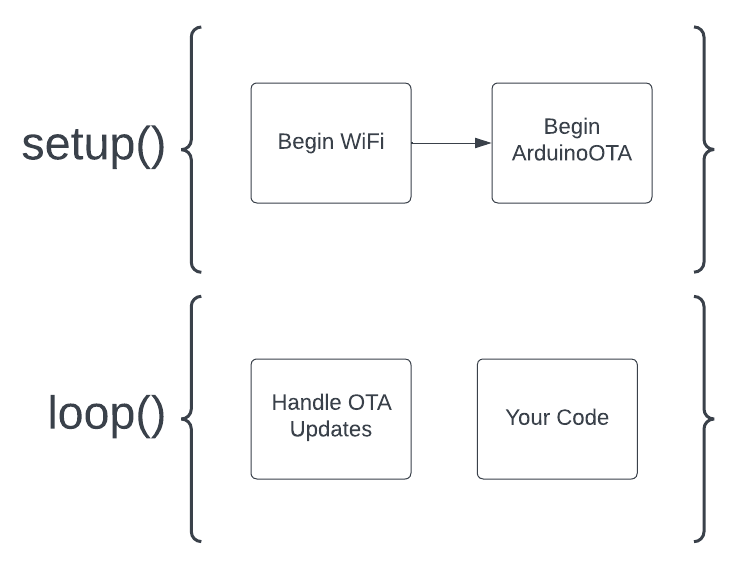
The next bit of code is in the setup() function:
void setup() {

  WiFi.begin(ssid, password);  // Connect to WiFi - defaults to WiFi Station mode

  // Ensure WiFi is connected
  while (WiFi.status() != WL_CONNECTED) {
    delay(500);
  }

  ArduinoOTA.begin();  // Starts OTA
}
The first thing we do is start the wifi connection using our credentials, and then wait to make sure we are connected. You could probably get away with skipping the wait part – it’s not necessary for OTA, but it’s common practice to make sure you’re actually connected to WiFi before continuing on with the program.
The final part of setup is beginning the over-the-air functionality, using the ArduinoOTA.begin() function.
The loop is even simpler:
void loop() {

  ArduinoOTA.handle();  // Handles a code update request

  // All loop your code goes here.
}
You see we have a single line of code in the loop, ArduinoOTA.handle(). This is the function that will handle incoming over-the-air update requests.
After this code is where you can write your own code to do whatever it is you want your ESP32 to do, like read sensors, blink LEDs, take over the world, etc…
And that is literally all the code you need to set up OTA for your ESP32! But there is one REALLY important thing to remember…
This Is Really Important for OTA
Everytime you upload code to your board using this OTA process, your new sketch MUST include at least the minimum OTA code shown above – or else your new sketch won’t be OTA capable!
Here’s the deal…this OTA code isn’t some special thing that runs as a “background” process of your ESP32. It’s not something you are “enabling” in the ESP32.
The code itself is what is making the OTA possible. If a program you upload to your ESP32 over-the-air doesn’t have this minimum OTA code included in it, you can’t make over-the-air updates to that board until you have physically connected it to your computer with a USB cable and upload a new sketch that does include the minimum OTS code.
Uploading Sketches Over-the-air to ESP32 Arduino Board
So how do you actually upload a new sketch to a board that has the OTA code running on it?
Turns out it’s crazy simple. (Got to love Arduino!)
First, you need to be using a computer that is connected to the same WiFi network that your ESP32 is connected to (Remember in the code where we did WiFi.begin()? Your computer needs to be connected to that same WiFi network).
Next simply open up the Arduino IDE (we are demonstrating this with Arduino IDE 2.x, but Arduino IDE 1.x works fine as well.)
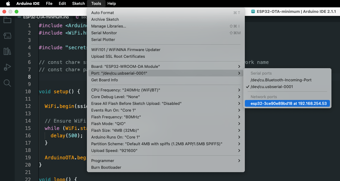
Now, go Tools>Port and you should see a new port listed under “network ports”.
This network port represents the connection to your ESP32 running the OTA code, now simply select the port and you can upload code to it just as if it were connected to a USB!
Just remember to include the minimum OTA code in your new sketch 😀
If you are using Arduino IDE 1.x you may have to close and reopen the IDE in order to see the network port listed.
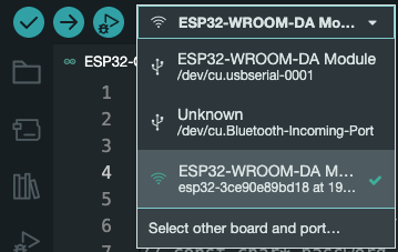
Another way to select the network port in Arduino IDE 2.x is to simply click the board and port drop down next to the Verify and Upload buttons at the top left. You should see the network port listed with a WiFi symbol in front of it.
Is there More to OTA than this?
The code we demonstrated here was the absolute minimum you need to get OTA working.
I wanted to keep it bare bones to make sure the basics are covered. But if you’d like to see more functionality then check out the ArduinoOTA example provided in the Arduino IDE.
To do this go to File>Examples>ArduinoOTA>BasicOTA. When you open up the sketch you’ll quickly realize there is a lot more going on – but it’s all good stuff and definitely worth exploring if you’re interested.
Try on You Own Challenge
It’s one thing to read a lesson, another thing entirely to do this on your own. Try a couple of these challenges to see if this is hitting home yet.
- Create a new sketch and write out the minimum code for the OTA yourself. Upload this…can you see your network port?
- And a simple LED circuit to one of your ESP32 pins. Now modify your minimum OTA sketch to blink an LED in the loop. Upload this new code…do you see the LED blinking?
- Modify the sketch again by adjusting the delay time of the LED blinking. Upload this new code – can you visually confirm your over-the-air update worked?
- Upload the BasicOTA sketch from File>Examples>ArduinoOTA>BasicOTA. See if you can follow some of the additional functionality
Where to go from Here
In this guide, we’ve discussed uploading sketches over-the-air to your ESP32 boards using the Arduino ArduinoOTA library and the Arduino IDE.
I really hope we have made it accessible for beginners (and useful for experienced enthusiasts as well!).
If you liked this style of training, and would like a clear road map to programming Arduino and using it to develop your own projects, then I think you’ll find our training program extremely useful.


i did everything just like you said. I added all the basic lines of code you wanted to add, and this is all I can get when I try to upload an update:
Uploading: [ ] 0%
09:04:59 [ERROR]: Error Uploading
09:04:59 [ERROR]: Error Uploading
I hope you can help me, cause my camera is up in a tree and I need to make updates to the esp32 cam without having to climb the tree and get the camera to update it.
Thank you so much for your help
Tony
Do you see your device listed as a network port? Is it in range of your WiFi?
Yes. Authanticaded. And shown in Arduino Port list 192.168.1.21. But “Error Uploading: [WinError 10054]”
What can I do
I would double check that you have the correct board type selected from the board selection drop down in the Arduino IDE.
good day,
I do not understand well the way to include the minimum code into the sketch I am going to upload using wifi.
Could you please post a short/ simple code ?
Thaks for all
regards
Great question… so the code that is shown at the top of this post – all that code you need to include every time you upload you sketch.
Think about that code at the the top as your “OTA template code”. You can customize it with your own code statements, but don’t remove any of it when you upload a new sketch.
Im using the Arudino Nano ESP32 and uploaded “BasicOTA”. I successfully uploaded “Blink” over my Wifi and it ran……so cool. When power is removed, the blink sketch will run when power reapplied, but the “Basic OTA” is no longer running. Is there a way to keep Basic OTA in non-volatile memory so that BasicOTA starts again and is ready for uploads over Wifi if power is removed and reapplied? thank you
Great question Robin!
Yes, there is. Everytime you upload a new sketch, your new sketch needs to include the OTA code. That is a key step. That way, your device will always be keeping an “ear out” for a firmware update.
Will this pared down OTA code work on an ESP8266 board? Or would that require some of the additional code from the Arduino OTA example? Thanks for the awesome videos by the way!
Should be pretty close! You’ll need to change the library from WiFi to ESP8266WiFi.h
I can confirm that it does indeed work with your suggested library change. This will be quite helpful!
Great! The main thing to remember for OTA is that you must include the OTA code in all the subsequent sketches you upload, otherwise, the board will not be looking for updates.