3 Ways to Power Arduino
In this lesson we are going to talk about three ways to power Arduino boards, namely the…
- Vin pin
- DC jack
- USB port
Each method has some quirks and limits you should be aware of, and we’ll do our best to highlight each!

Arduino power section schematic
In our discussion here, we are going to use an Arduino UNO as the base example – much of what we cover can be extended to other common Arduino boards, but in each case you’ll need to double check for your specific model.
Programming Electronics Academy members, check out the Powering Projects Course to dive into the circuit details of powering an Arduino.
Not a member yet? Sign up here.
We are going to use the Arduino UNO schematic to inform our discussion – we’ll be looking at the power section.

It seems like a lot going on – to simplify this a bit further we’ll reduce it down to this block diagram.

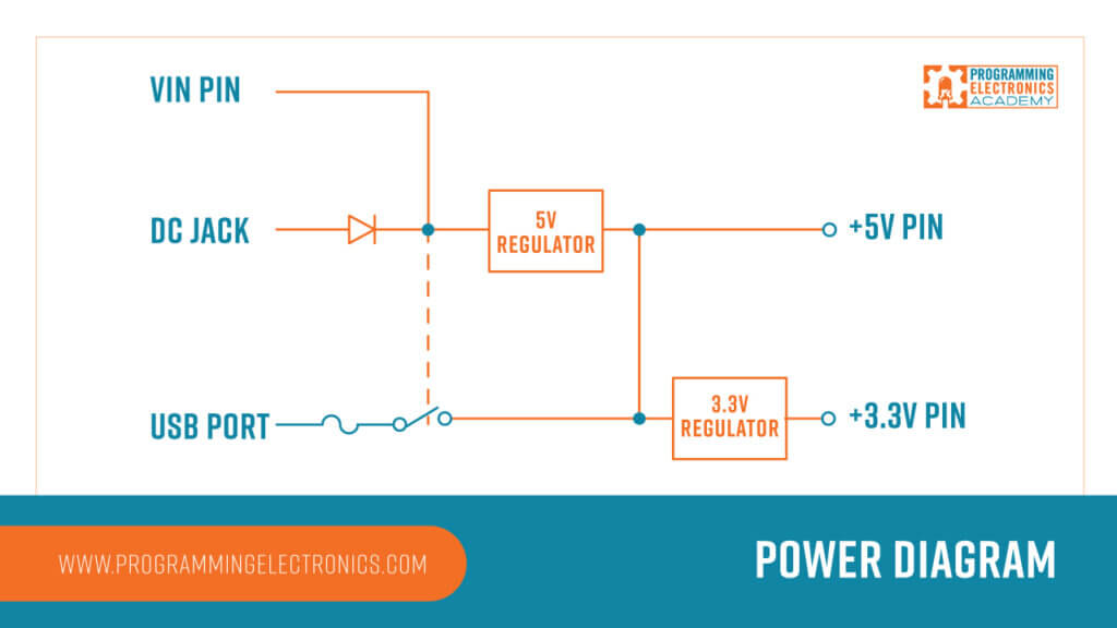
When you see “USB PORT”, just imagine that’s where you plug your USB cable in, for “DC JACK” – imagine that where you plug your DC Jack in. And for the “VIN PIN”, that just the hole marked Vin on the power rail of an Arduino Board.
On the right side we have the 5V and 3.3V pins. In between we have some components that I’ll explain shortly.
Powering Arduino w/ the DC Jack
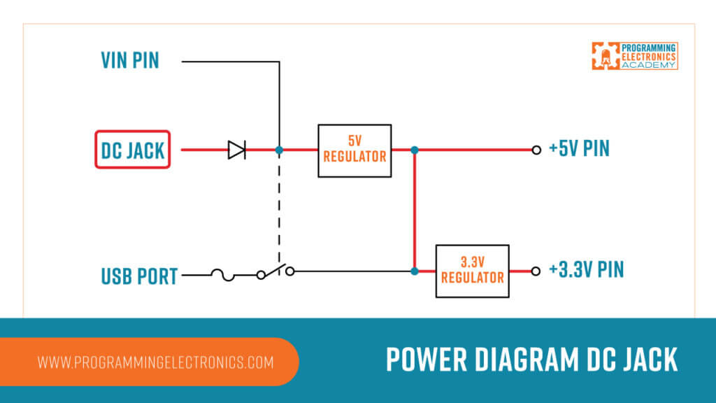
Let’s start with powering an Arduino with the DC jack. Let’s say you hook up a wall wort power supply, or a battery pack to that DC jack – what happens? Per the diagram you can see it powers the 5V regulator on the board.
What’s so special about 5V? Well 5V is right in the range the microcontrollers on the Arduino board need in order to operate.
| Minimum Input voltage | Maximum Input voltage | Maximum Output current | |
| +5V regulator | 6.2V | 20V | 1A |
| +3.3V regulator | 3.58V | 16V | 150mA |
The 5V regulator requires a min input voltage of 6.2 volts and can take a maximum input voltage of 20V – so the power supply you hook up to your DC jack needs to be in that range for voltage. The sweet spot is more like 7-12 volts, if your power supply is much higher than that, you’re wasting a lot of power on that 5V regulator in the form of heat dissipation.
The DC jack is 2.1mm center-positive plug. It important that the plug you use is center positive. But just in case you accidentally use a center negative plug and reverse the polarity – the circuit has a diode that protects against that.
Programming Electronics Academy members, check out the Powering Projects Course to learn more about powering your projects.
Not a member yet? Sign up here.
OK – one more thing about that 5V regulator, it can provide up to 1A of current.
What’s the big deal about the current? Well here is the deal – all the electronics stuff you attach to your Arduino board is going to consume current. In fact, the components on the Arduino UNO board itself will be using around 25mA of current.
So if you go attaching a bunch of stuff to your 5V power rail that draws a bunch of current, like say servos that are going to be under a high load, then you’ll be drawing more current than what the regulator is rated for, and you’ll burn up the part – something you’d want to avoid.
Notice that the 5V regulated power supply also power the 3.3V regulator on the board, which then provides power to the 3.3V pin.
There’s one more important thing to mention: the diode in line with the DC jack has a voltage drop of roughly 0.7 volts. If you provide the DC jack with 7 volts, the 5V regulator will see an input of 7V – 0.7V = 6.3 V, which is getting uncomfortably close to the minimum 5V regulator input of 6.2V. If you use the DC jack, you may want to bump up the input voltage a bit.
Powering with Vin Pin
Now let’s shift to Vin. Vin is a pin on the Arduino power rail where you can directly hook a power supply line into the board. The voltage requirement is the same as with the DC jack, because you’ll notice Vin is supplying power to the 5V regulator as well – in fact powering with Vin is almost exactly like powering with the DC jack.

What you don’t have on the Vin pin is any reverse polarity protection – because there is no diode protection there – so you’ll want to make sure to connect positive voltage to this pin. Also, with no diode, there is also no voltage drop.
USB and Vin/DC jack together
One last thing…
Notice the dotted connection between the DC Jack and Vin circuitry to what we have drawn as a switch. That switch is actually a P-channel MOSFET, that you can think of as a switch – either being open (no current able to flow), or closed (current able to flow).
IF the voltage at above that switch is greater than 6.6V, then it opens the switch, which shuts off the power supply line form the USB cable – what this mean? It means, if you are powering using Vin or the DC jack, then the power from the USB cable will be disabled. This does not mean you won’t be able to use the USB data lines – those will work fine – it’s just the USB won’t be providing any power to the board.
Powering with USB
OK, so we have talked about Vin and the DC Jack, now let’s talk about USB,
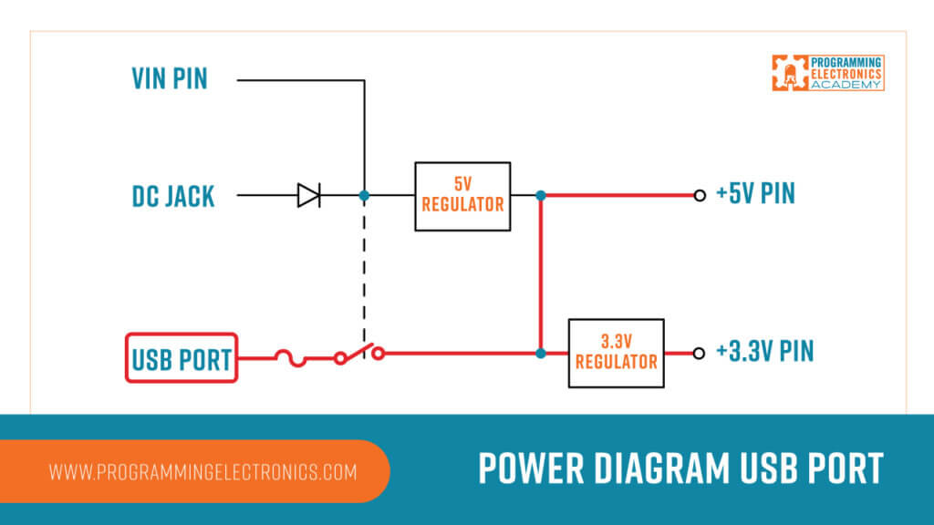
What’s cool about USB is that it provides a regulated 5V supply, so the circuit skips over the 5V regulator, and provides power the Arduino board, and is available at the 5V pin on the Arduino.
It does power the 3.3V regulator.
As far as current goes USB can provide is 500mA for USB 1 and 2, and 900mA for USB3.
- USB1.x and USB2 provide 5V +/-5% with 500 mA maximum current
- USB3 provides 5V +/-5% with 900 mA maximum current
I have already mentioned that drawing more current than you components are rated for can cause damage to your Arduino board, but what happens when you draw more current than your USB port can provide?
Here is what is neat about the Arduino USB power circuit. Let’s say you do draw more than 500mA of current – where there is a thermal polyfuse that will tripped – this will open the circuit (until the polyfuse resets) It’s there to protect your USB port in the case you do overdraw current – which hey, is good to know.
Ideally, you’re not doing that in the first place, but hey stuff happens.


thanks for sharing and the email that brought me here. I had hoped that a solar panel battery source was going to be an option. Oh well, I still enjoyed the info and learned a thing or two. Peace and Thanks. Scotty
We’ll have to explore that as an add on for this lesson! Thanks Scotty!
I really need that too, I’m working with a project which require powering by solar panel (with battery).
where I could find powering Arduino Course?
Thanks Mike, so clear and so important to know
Thanks David! Glad you found it helpful!
Thanks for this very helpful tutorial, it might be basic stuff!. but it was stuff I didn’t know about.
Stay safe and enjoy your day 🙂
John, from sunny Doncaster ( UK )
Glad it helped John – thanks for the note!